Laparoscopic cutting stapler

A stapler and laparoscopic technology, applied in the field of medical devices, can solve the problems of triangular alveolar not having one-way movement, flexibility constraints, and narrow operating space

A stapler and laparoscopic technology, applied in the field of medical devices, can solve the problems of triangular alveolar not having one-way movement, flexibility constraints, and narrow operating space

CN105596049BActive Publication Date: 2017-12-26CHANGZHOU KANGDI MEDICAL STAPLER

Image

  • Laparoscopic cutting stapler
  • Laparoscopic cutting stapler
  • Laparoscopic cutting stapler

Examples


Embodiment Construction

[0036] The present invention is described below in conjunction with accompanying drawing.

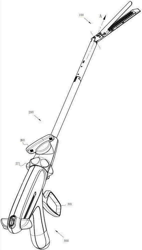
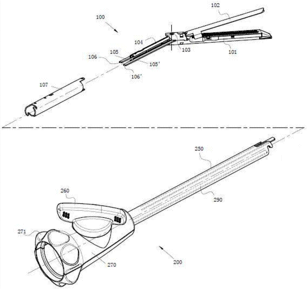
[0037] At present, the known laparoscopic cutting stapler is used in surgical operations, and the stapler includes a butt-mounted execution assembly 100, a jaw direction adjustment mechanism 200, and a stapler driving part 300; the execution assembly 100 includes at least an upper jaw with a molded groove Mouth 102, lower jaw 101 with staple cartridge, joint connecting plate 105, elastic push plate 104 and component sleeve 107; stapler driving part 300 at least includes shell and operable handle 301; jaw direction adjustment mechanism 200 is set The front end of the stapler driving part 300 is connected by a connecting rib 272 .

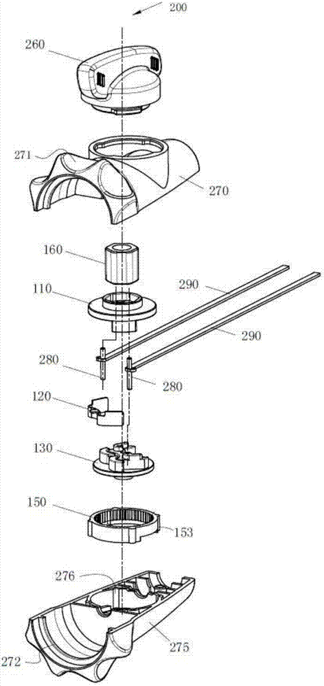
[0038] as attached Figure 1-9 As shown, in the first embodiment of the present invention, the jaw direction adjustment mechanism 200 includes a joint knob 260, a main turntable 110, a shrapnel assembly 120, a slave turntable 130, a ring gear 150, a transmiss...


PUM


Abstract

The invention discloses a laparoscopic cutting stapler, which comprises an executive assembly, a jaw direction adjustment mechanism and a stapler driving part; the jaw direction adjustment mechanism comprises a joint knob, a main turntable, a shrapnel assembly, a slave turntable, a ring gear, and a transmission shaft , pin shaft, swivel head, adjusting sleeve and 2 joint push rods; the main turntable is provided with a main boss; the slave turntable is provided with a mounting position, a slave boss and a pin hole; the shrapnel assembly includes two elastically set snaps The ring gear is fixed in the rotating head, and its inner ring is provided with evenly distributed teeth; when the joint knob is turned to adjust the jaws to turn, the shrapnel assembly is snapped into the ring gear in time, limiting the rotation from the turntable, effectively ensuring the operation For the problem of jaw swing back during the process, it is easier and labor-saving to operate the adjustment mechanism of the jaw direction; the sound from the beating of the shrapnel makes the jaw direction adjustment mechanism of the stapler have dual reminder effects of feeling and sound.

Description

technical field [0001] The invention relates to a surgical medical instrument, in particular to a laparoscopic cutting stapler capable of bidirectional locking in multiple positions, belonging to the technical field of medical instruments. Background technique [0002] The application number of the Chinese invention patent "Cutting Stapler Suitable for Minimally Invasive Surgery" is CN201310263622.9, and the following is briefly described as Patent 1, which discloses a surgical instrument. The rotating joint knob drives the joint base to rotate synchronously, and the 2 A pin shaft drives two joint push rods to slide back and forth, so that the two joint connecting plates inside the executive component drive the jaws to rotate and adjust around the hinge pins, and the top ball of the positioning bead is embedded in the joint seat for corresponding positioning under the action of the spring force. In the groove, the positioning beads block the joint seat by means of friction a...

Claims


Application Information

Patent Timeline
26 Dec 2017
Publication
CN105596049B
IPC
A61B17/072
CPC
A61B17/07207; A61B2017/2927
Inventors
杨卫民