Forming delay mechanism for die

A technology of time-delay mechanism and mold, which is applied in the direction of forming tools, manufacturing tools, metal processing equipment, etc., can solve the problems of short forming time, too late stress release, no consideration of forming time, etc., and achieve reliable work, good forming effect, and extended Effect of forming action time

Active Publication Date: 2016-05-25
HUNAN UNIV +2
View PDF6 Cites 10 Cited by
  • Summary
  • Abstract
  • Description
  • Claims
  • Application Information

AI Technical Summary

Problems solved by technology

The traditional design does not consider the forming time when designing the structure of the forming process. The forming time is extremely short, and the stress after forming is too late to release, resulting in a large springback after forming.

Method used


Image

  • Forming delay mechanism for die
  • Forming delay mechanism for die
  • Forming delay mechanism for die

Examples


Embodiment Construction

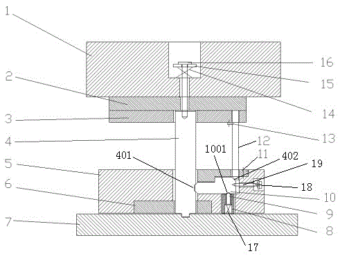
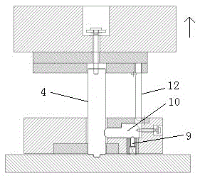
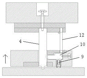
[0013] Such as figure 1 As shown, the forming delay mechanism of the mold provided by the present invention includes an upper mold part, a discharge part and a die plate, and the upper mold part includes an upper backing plate 2 on which an upper mold base 1 is located and a punch fixing Plate 3, the upper mold part is provided with a punch 4 and a vertical bar 12 parallel to the punch 4, the punch 4 passes through the attachment 15 placed in the upper die base 1, the return spring 14 and passes through the upper backing plate 2 and the screw 16 fixed on the upper mold base 1 is hoisted in the punch fixing plate 3, and the side of the punch 4 is provided with a groove 401; the vertical rod 12 is installed on the punch fixing plate 3 through the vertical rod cover plate 13 On the top, the head of the vertical rod 12 is wedge-shaped; the discharge part includes a discharge plate seat 5, a small discharge plate 6 and a push rod cover 11, and the discharge part is provided with a ...


PUM


Abstract

The invention discloses a forming delay mechanism for a die. The forming delay mechanism comprises a die loading part, an unloading part and a female die plate, wherein an elastic male die with a wedge-shaped groove formed in the side surface and a vertical rod parallel to the male die are arranged on the die loading part, and the head part of the vertical rod is wedge-shaped; an elastic push rod and an elastic limiting rod are arranged on the unloading part, the elastic push rod is matched with the wedge-shaped groove of the male die and the head part of the vertical rod by the wedge-shaped head part and an inclined plane at the tail part, a groove is formed in the side surface of the push rod, and the elastic limiting rod is matched with the groove of the push rod by the spherical head part and connected with the female die plate. The forming delay mechanism can prolong the forming action time of the male die and play a pressure maintaining role, has a better forming effect, achieves pressure maintaining to move mechanically, and is reliable in operation.

Description

technical field [0001] The invention belongs to molds, in particular to a forming delay mechanism of a mold. Background technique [0002] In one stamping stroke of the progressive blanking forming die, if the downward forming depth is not large, it is generally punched first and then formed, which is determined by the height of the punch. The height of the blanking punch of the traditional mold is the benchmark for the design of the forming punch. At the beginning of punching, the forming punch is far from touching the sheet. Only when the distance between the upper backing plate and the sheet is the forming punch When the height is high, the lower surface of the forming punch touches the sheet, and then the forming area is driven by the punch to move down to the forming depth. Forming force, so the forming time is only a small part of a stamping stroke. The traditional design does not consider the forming time when designing the structure of the forming process. The form...

Claims


Application Information

Patent Timeline
Patent Type & Authority Applications(China)
IPC IPC(8): B21D37/12
CPCB21D37/12
Inventor 毛建中史众宁建华海争平宋建力
Owner HUNAN UNIV
Why Eureka
Try Eureka