Vertical multi-track pulling robot for section bars

A multi-track, robot technology, applied in the direction of manipulators, manufacturing tools, etc., can solve the problems of inability to guarantee the straightness and flatness of profile traction, reduce the occupied area, etc., and achieve the effect of easy control, reduced occupied space, and flexible operation

Active Publication Date: 2016-05-25
广东省智行机器人科技有限公司
View PDF6 Cites 5 Cited by
  • Summary
  • Abstract
  • Description
  • Claims
  • Application Information

AI Technical Summary

Problems solved by technology

[0009] The purpose of the present invention is to overcome the shortcomings and deficiencies in the prior art, and provide a vertical profile multi-track traction robot with flexible operation. Improve the efficiency of profile traction; at the same time, the multi-track traction robot can not only reduce the footprint, thereby reducing production costs; and it is not affected by the ground conditions, which can effectively solve the problem that the straightness and straightness of profile traction cannot be guaranteed due to uneven ground The problem of degree, thereby improving the quality of profile traction processing

Method used


Image

  • Vertical multi-track pulling robot for section bars
  • Vertical multi-track pulling robot for section bars
  • Vertical multi-track pulling robot for section bars

Examples


Embodiment 1

[0055] This embodiment takes the vertical formation of a double-track traction robot as an example to describe the following.

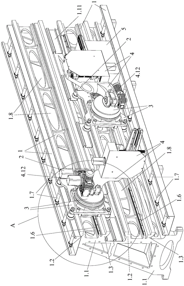
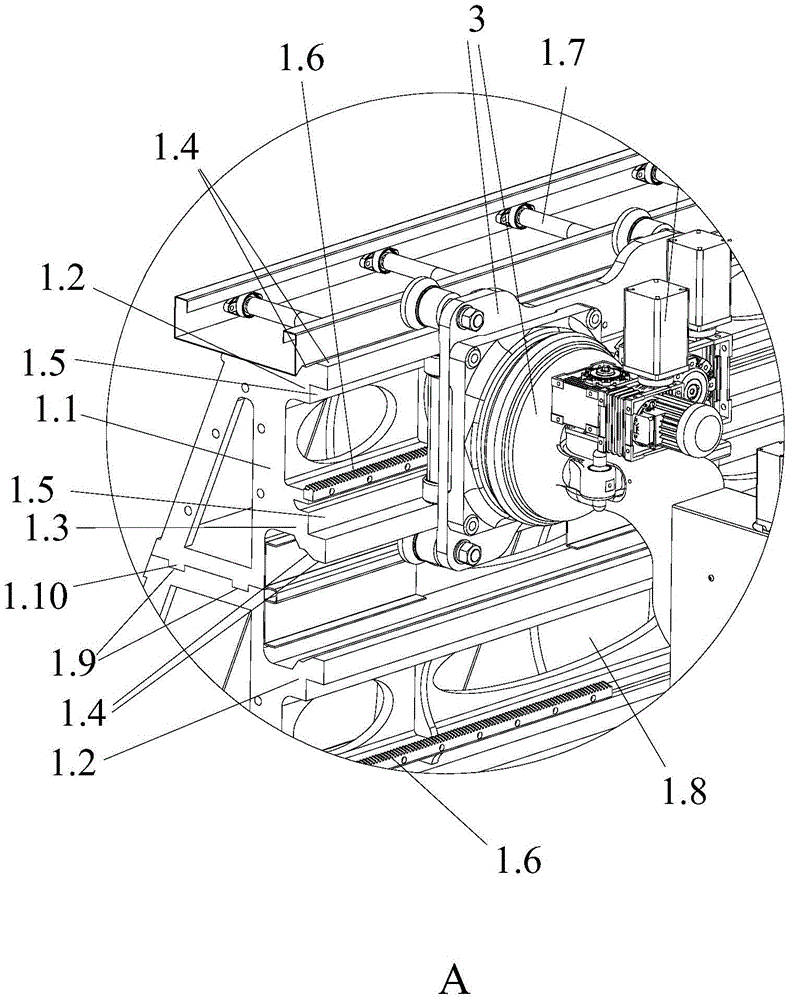
[0056] like Figures 1 to 7 As shown, the vertical profile double-track pulling robot of the present invention is used to pull the profile at the discharge port. The traction robot includes a control mechanism 5 and two traction units, wherein each traction unit includes a vertical walking track 1, a mechanical arm for clamping traction profiles, a transmission mechanism and a drive mechanism 2 for connecting with the transmission mechanism, Wherein, the mechanical arm is buckled on the side of the vertical walking track 1, and is slidably connected with the side of the vertical walking track 1, so that the mechanical arm is suspended on the side of the vertical walking track 1 for walking and moving; The transmission device one 3.8 on the mechanical arm and the transmission device two 1.6 on the vertical walking track 1, the control mechanism 5 is c...

Embodiment 2

[0070] The only difference between this embodiment and the implementation is that this embodiment is a vertical profile multi-track traction robot. The mechanical arms of the two traction units are suspended on the vertical walking track for coordinated and alternate walking movement, so as to realize the traction of the profiles in a coordinated and alternate manner.

[0071] The structure of each traction unit in this embodiment is consistent with the first embodiment.

Embodiment 3

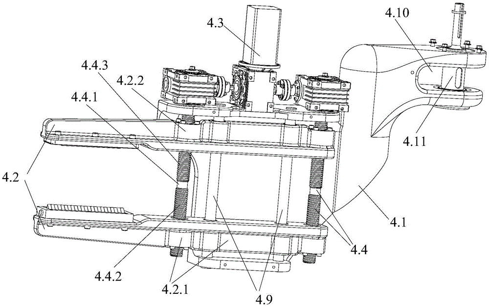
[0073] The difference between this embodiment and the first embodiment is only that the positions of the threaded part 1 with a left-handed thread and the threaded part 2 with a right-handed thread are exchanged. In the present invention, the opening and closing movement of the first splint and the second splint can be realized as long as the screw rotation directions of the first screw and the second screw are opposite.

[0074] Other structures of this embodiment are consistent with Embodiment 1.


PUM


Abstract

The invention provides a vertical multi-track pulling robot for section bars. The vertical multi-track pulling robot comprises M pulling units and a control mechanism. Each pulling unit comprises a vertical travel track, a mechanical arm, a transmission mechanism and a driving mechanism, the mechanical arms are used for clamping and pulling the section bars, the driving mechanisms are used for being connected with the transmission mechanisms, and the mechanical arms are clipped on the side surfaces of the vertical travel tracks and are slidably connected with the side surfaces of the vertical travel tracks, so that the mechanical arms can be suspended on the side surfaces of the vertical travel tracks and can travel and move; the transmission mechanisms comprise first transmission gears and second transmission gears, the first transmission gears are arranged on the mechanical arms, and the second transmission gears are arranged on the vertical travel tracks; the M pulling units are spliced with one another in an overlapped manner by the aid of the vertical travel tracks, and the mechanical arms of each two adjacent pulling units are suspended on the corresponding vertical travel tracks and can cooperatively alternately travel and move, so that the section bars can be pulled in a cooperative alternative manner. The vertical multi-track pulling robot has the advantages that the section bars can be fully automatically pulled in a multi-track mode according to production requirements, and accordingly the section bar pulling efficiency can be improved.

Description

technical field [0001] The invention relates to the technical field of metal processing, and more specifically relates to a vertical profile multi-track traction robot. Background technique [0002] In the processing technology of metal profile extrusion and pull forming, the specific production process is: after the metal profile is extruded by the extruder, the aluminum profile produced is discharged from the discharge port of the extruder. A discharge platform is arranged in front of the discharge port of the metal profile, and a cutting machine or other processing equipment is installed between the discharge platform and the discharge port. When discharging, in order to prevent the metal profile from twisting, after the metal profile comes out of the mold mouth, a clamp is required to pull it along the guide rail. [0003] The traditional operation method is to manually pull the metal profile, and after reaching the specified length, it will be cut off by the cutting ma...

Claims


Application Information

Patent Timeline
Patent Type & Authority Applications(China)
IPC IPC(8): B25J5/02
CPCB25J5/02
Inventor 卢新建廖子剑唐崇斌
Owner 广东省智行机器人科技有限公司
Why Eureka
Try Eureka