Vertical profile single-rail traction robot

A single-track, robot technology, applied in the direction of manipulators, manufacturing tools, etc., can solve problems such as the inability to guarantee the straightness and straightness of profile traction, and achieve the effect of easy control, strong flexibility, flexible movement and walking

Active Publication Date: 2016-05-11
广东泰格威机器人科技有限公司
View PDF7 Cites 8 Cited by
  • Summary
  • Abstract
  • Description
  • Claims
  • Application Information

AI Technical Summary

Problems solved by technology

[0009] The object of the present invention is to overcome the shortcomings and deficiencies in the prior art, and provide a vertical profile single-track traction robot with flexible operation. This traction robot can not only reduce the floor area, thereby reducing production costs; It can effectively solve the problem that the straightness and flatness of profile traction cannot be guaranteed due to uneven ground, thereby improving the quality of profile traction processing

Method used


Image

  • Vertical profile single-rail traction robot
  • Vertical profile single-rail traction robot
  • Vertical profile single-rail traction robot

Examples


Embodiment 1

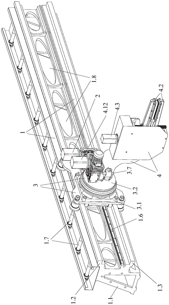
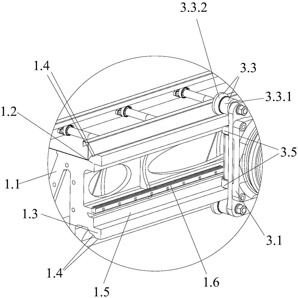
[0049] Such as Figures 1 to 7 As shown, the vertical profile single-track pulling robot of the present invention is used to pull the profile at the discharge port. The traction robot includes a vertical walking track 1, a mechanical arm for clamping traction profiles, a transmission mechanism, a drive mechanism 2 for connecting with the transmission mechanism and a control mechanism (not shown), wherein the mechanical arm is buckled on the vertical on the side of the vertical walking track 1, and is slidingly connected with the side of the vertical walking track 1, so that the mechanical arm is suspended on the side of the vertical walking track 1 for walking and moving; the transmission mechanism is a transmission device-3.8 respectively arranged on the mechanical arm And the transmission device two 1.6 on the vertical walking track 1, the control mechanism is connected with the drive mechanism 2 and the mechanical arm signal respectively, and the transmission device one 3.8...

Embodiment 2

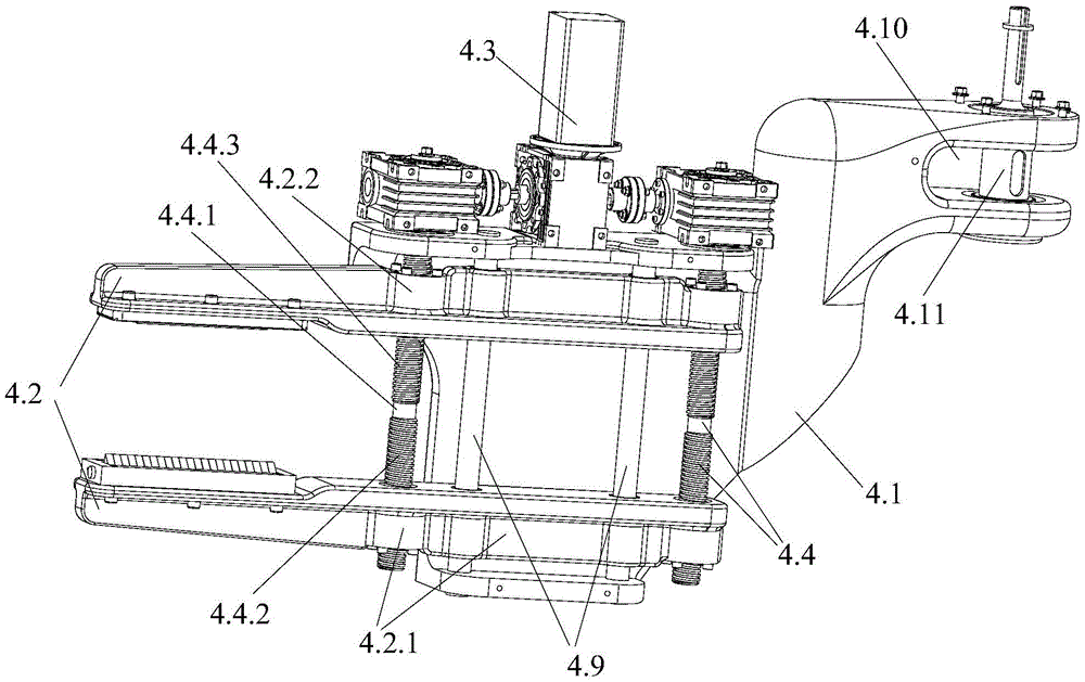
[0062] The difference between this embodiment and the first embodiment is only that the positions of the threaded part 1 with a left-handed thread and the threaded part 2 with a right-handed thread are exchanged. In the present invention, the opening and closing movement of the first splint and the second splint can be realized as long as the screw rotation directions of the first screw and the second screw are opposite.

[0063] Other structures of this embodiment are consistent with Embodiment 1.

Embodiment 3

[0065] The only difference between this embodiment and Embodiment 1 is that the guide wheels of the present invention can be provided with six or eight etc. according to the size of the frame body 1, and the guide wheels are distributed symmetrically at the bottom of the frame body 1 up and down, and the relative guide wheels up and down The wheels are used to buckle on the side of the vertical walking track and be slidably connected with the vertical walking track. In this embodiment, the upper and lower relative guide wheels can be buckled on the side of the vertical track to realize the stable suspension and moving of the frame body one.

[0066] Similarly, one, two, three or more support wheels can be set according to the requirements, so as to avoid the phenomenon of deviation in the movement of the frame body, and further ensure the straightness and straightness of the movement of the mechanical arm.

[0067] Other structures of this embodiment are consistent with Embodi...


PUM


Abstract

The invention provides a vertical profile single-rail traction robot. The vertical profile single-rail traction robot comprises a vertical walking rail, a mechanical arm for clamping and towing a profile, a transmission mechanism, a driving mechanism for connecting with the transmission mechanism, and a control mechanism; the mechanical arm is buckled on the side surface of the vertical walking rail, and is slidingly connected with the side surface of the vertical walking rail to realize walking movement by hanging on the side surface of the vertical walking rail; the transmission mechanism consists of a transmission device 1 arranged on the mechanical arm and a transmission device 2 arranged on the vertical walking rail; and the control mechanism is respectively in signal connection with the driving mechanism and the mechanical arm. The vertical profile single-rail traction robot adopts the mechanical arm as an actuation mechanism for towing the profile, and is flexible in operation and convenient for control. Meanwhile, the vertical profile single-rail traction robot can shrink the floor area to reduce the production cost, and is not influenced by the ground condition to effectively solve the problem of incapability of guaranteeing the profile towing straightness caused by uneven ground so as to improve the profile towing processing quality.

Description

technical field [0001] The invention relates to the technical field of metal processing, and more specifically, relates to a vertical profile single-track traction robot. Background technique [0002] In the processing technology of metal profile extrusion and pull forming, the specific production process is: after the metal profile is extruded by the extruder, the aluminum profile produced is discharged from the discharge port of the extruder. A discharge platform is arranged in front of the discharge port of the metal profile, and a cutting machine or other processing equipment is installed between the discharge platform and the discharge port. When discharging, in order to prevent the metal profile from twisting, after the metal profile comes out of the mold mouth, a clamp is required to pull it along the guide rail. [0003] The traditional operation method is to manually pull the metal profile, and after reaching the specified length, it will be cut off by the cutting ...

Claims


Application Information

Patent Timeline
Patent Type & Authority Applications(China)
IPC IPC(8): B25J5/02
CPCB25J5/02
Inventor 卢新建廖子剑唐崇斌
Owner 广东泰格威机器人科技有限公司
Why Eureka
Try Eureka