An asphalt pavement cooling device

A cooling device and asphalt pavement technology, which is applied to roads, roads, pavement details, etc., can solve the problems of low cooling efficiency and small cooling area, and achieve the effect of increasing the coverage area, improving the cooling efficiency and saving space.

Active Publication Date: 2018-01-19
NANTONG ROAD & BRIDGE ENG CO LTD
View PDF9 Cites 0 Cited by
  • Summary
  • Abstract
  • Description
  • Claims
  • Application Information

AI Technical Summary

Problems solved by technology

[0007] The invention provides an asphalt pavement cooling device, which solves the technical problems of the existing road surface cooling device such as small cooling area and low cooling efficiency.

Method used


Image

  • An asphalt pavement cooling device
  • An asphalt pavement cooling device
  • An asphalt pavement cooling device

Examples


Embodiment 1

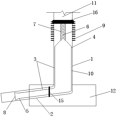
[0025] Embodiment 1: as figure 1 As shown, the base 12 is provided with an evaporation pipe section and a condensation pipe section, and the condensation pipe section includes an outer pipe 1 of the condensation pipe and an inner pipe 4 of the condensation pipe. In the shape of a wine bottle, the gas channel changes from wide to narrow, which will accelerate the airflow, thereby speeding up the speed of the gaseous working medium entering the outer tube from the inner tube, avoiding the early liquefaction of the gaseous working medium due to too slow gas outlet, and liquefaction in the outer tube The working medium can flow into the liquid working medium reflux tank along the outer contour of the wine bottle.

[0026] The top of the inner tube 4 of the condensation tube is provided with an air outlet 7, and the air outlet 7 is engraved with an air outlet 6 of the inner tube of the condensation tube with a diameter of 10 mm and a distance between centers of 15 mm, so that the g...

Embodiment 2

[0032] Embodiment 2: as figure 1 As shown, the base 12 is provided with an evaporation pipe section and a condensation pipe section, and the condensation pipe section includes an outer pipe 1 of the condensation pipe and an inner pipe 4 of the condensation pipe. In the shape of a wine bottle, the gas channel changes from wide to narrow, which will accelerate the airflow, thereby speeding up the speed of the gaseous working medium entering the outer tube from the inner tube, avoiding the early liquefaction of the gaseous working medium due to too slow gas outlet, and liquefaction in the outer tube The working medium can flow into the liquid working medium reflux tank along the outer contour of the wine bottle.

[0033] The top of the inner tube 4 of the condensation tube is provided with an air outlet 7, and the air outlet 7 is engraved with an air outlet 6 of the inner tube of the condensation tube with a diameter of 10 mm and a distance between centers of 15 mm, so that the g...

Embodiment 3

[0039] Embodiment 3: as figure 1 As shown, the base 12 is provided with an evaporation pipe section and a condensation pipe section, and the condensation pipe section includes an outer pipe 1 of the condensation pipe and an inner pipe 4 of the condensation pipe. In the shape of a wine bottle, the gas channel changes from wide to narrow, which will accelerate the airflow, thereby speeding up the speed of the gaseous working medium entering the outer tube from the inner tube, avoiding the early liquefaction of the gaseous working medium due to too slow gas outlet, and liquefaction in the outer tube The working medium can flow into the liquid working medium reflux tank along the outer contour of the wine bottle.

[0040] The top of the inner tube 4 of the condensation tube is provided with an air outlet 7, and the air outlet 7 is engraved with an air outlet 6 of the inner tube of the condensation tube with a diameter of 10 mm and a distance between centers of 15 mm, so that the g...


PUM


Abstract

The application discloses an asphalt pavement cooling device, which includes two main parts: an evaporating pipe section and a condensing pipe section; the condensing pipe section includes the outer pipe of the condensing pipe and the inner pipe of the condensing pipe; When the temperature is high, the working fluid filled in the device will spontaneously circulate in gas-liquid state, thereby dissipating the heat of the road surface into the air, and reducing the asphalt road surface rutting, oil flooding, and pushing and other diseases caused by the rise in temperature; a single condensation pipe is connected to multiple One evaporating tube increases the cooling area of ​​a single condensing tube, and the cooling efficiency is greatly improved; the condensing tube can be integrated with street lamps, billboards and other road ancillary facilities without affecting the appearance.

Description

technical field [0001] The invention relates to the field of cooling devices, in particular to an asphalt pavement cooling device. Background technique [0002] The hot rod is a heat conduction system in which vapor and liquid flow in opposite directions. It is a sealed tube filled with a certain amount of working fluid (such as nitrogen, propane, carbon dioxide, etc.), the upper end is a condenser with cooling fins, the lower end is an evaporator with working fluid, and the middle is an adiabatic section. When the temperature of the condenser is lower than the temperature of the evaporator, the liquid working medium in the evaporator absorbs heat and evaporates. Under the action of the pressure difference, the steam rises to the end of the condenser, releases the latent heat of vaporization, and dissipates heat through the heat sink. The steam The working fluid is also cooled and condensed into liquid beads. Under the action of gravity, the liquid beads flow back to the ev...

Claims


Application Information

Patent Timeline
Patent Type & Authority Patents(China)
IPC IPC(8): E01C11/24
Inventor 高秀美季海萍王丽单光明杨阳
Owner NANTONG ROAD & BRIDGE ENG CO LTD
Why Eureka
Try Eureka