
Traffic cableway bridge reinforced concrete bridge deck slab

A technology for bridge decks and car dealerships, applied in bridges, bridge parts, bridge construction, etc., can solve the problems of poor durability of bridge deck components, poor bridge deck traffic performance, etc., and achieve convenient on-site assembly and construction, simple structure, and durability of components. Good results

Inactive Publication Date: 2016-08-24
景天虎
View PDF5 Cites 0 Cited by
  • Summary
  • Abstract
  • Description
  • Claims
  • Application Information

AI Technical Summary

Problems solved by technology

[0004] In order to overcome the defects of poor traffic performance and poor durability of bridge deck components in existing cableway bridges, the invention provides a bridge deck structure made of reinforced concrete

Method used


Image

  • Traffic cableway bridge reinforced concrete bridge deck slab
  • Traffic cableway bridge reinforced concrete bridge deck slab
  • Traffic cableway bridge reinforced concrete bridge deck slab

Examples


Embodiment 1

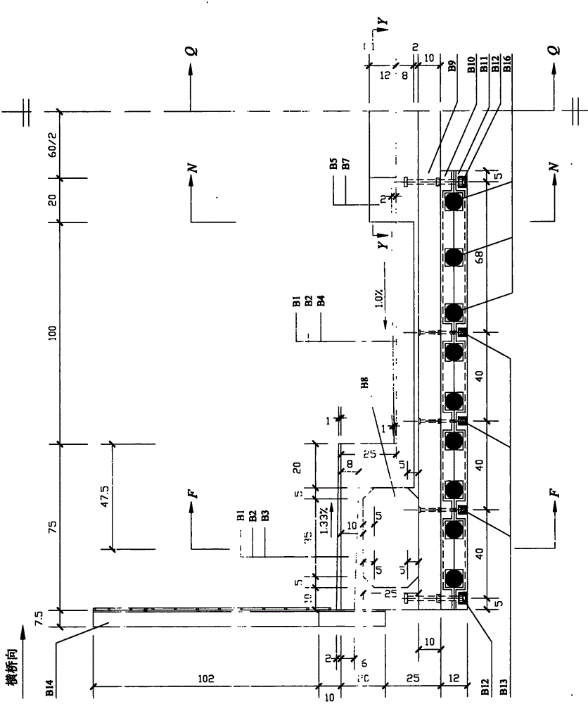
[0043] This embodiment is suitable for the construction of ordinary bridge plates. Taking a cableway bridge with a main span of 438m as an example, the design vehicle load model is 3×550kN, and the distance between vehicles is 150m.

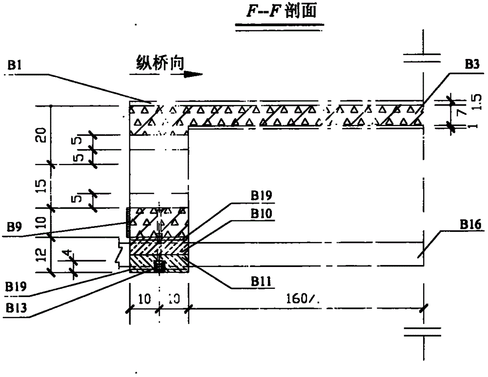
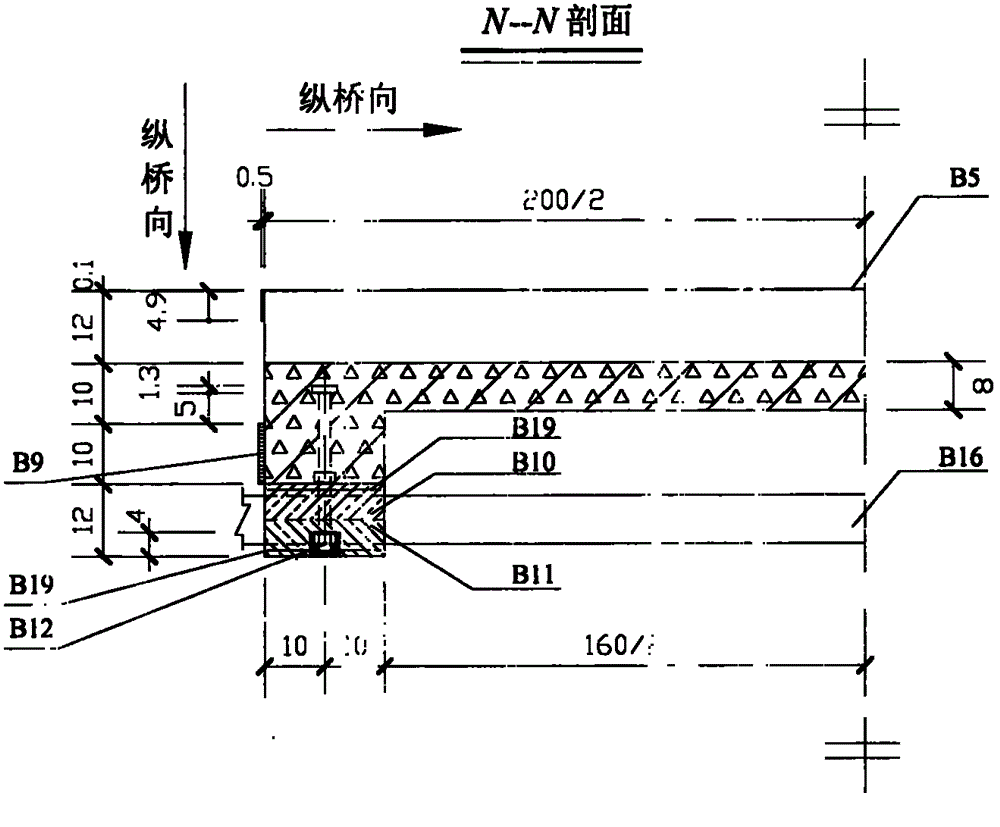
[0044] like figure 1 As shown, the deck structure layers of the sidewalk are asphalt sand wear layer (B1), JBS waterproof coating (B2), and C40 reinforced concrete sidewalk slab (B3) from top to bottom. The C40 reinforced concrete sidewalk slab (B3) is a variable-thickness cantilever slab, and the thickness of the cantilever end and root are 6cm and 8cm respectively. The bridge deck structural layers of the carriageway are asphalt sand wear layer (B1), JBS waterproof coating (B2), and C40 reinforced concrete carriageway slab (B4) from top to bottom. The thickness of the C40 reinforced concrete roadway slab (B4) is 8cm. The JBS waterproof coating (B2) should be applied after the bridge deck joint structure is installed, and the asphalt sand abr...

Embodiment 2

[0056] This embodiment is suitable for the construction of the beam deck. Taking a cableway bridge with a main span of 438m as a design example, the design vehicle load is 3×550kN and the distance between vehicles is 150m.

[0057] like Figure 23 , Figure 24 ,and Figure 25 As shown, most of the structures in the cross-section of the beam bridge deck are the same as those of the ordinary bridge deck, and its longitudinal bridge length is equal to the top surface width of the upper flange of the I50c steel beam (B28) supporting it. Its central part is no longer provided with a hole-retaining area, but the central opening side stringer (B7) remains to form an inner curb that guides the wheels to travel in a limited area. The beam zinc-iron cover plate (B5 ') is also much shorter than the common zinc-iron cover plate (B5), but its upper surface will still be painted with black road reflective paint strips (B17) and yellow road reflective paint strips (B18). Use M12×260-Q sq...


PUM


Abstract

A cableway bridge deck slab with excellent passing performance and endurance is made of reinforced concrete material; the lower portion of a seam between two adjacent bridge deck slabs is glued with a wood joint filling plate with anticorrosion treatment, and the upper portion is provided with a specific seam structure formed by reeling an upper zinc iron sheet and a lower zinc iron sheet; the bridge deck slab and bridge deck cables are connected through pre-buried lag bolts; the top surface of the bridge deck slab and top surface of the seam structure are paved by bridge deck pavement layers: a JBS fiber enhanced bridge deck waterproof layer and an asphaltic sand abrasion layer; two ends of an end floor beam of the bridge deck slab and the slab center zone are provided with holes, the center hole area is covered by the zinc iron sheet, and the top surface of the zinc iron sheet is painted with traffic guide signs; the bridge deck slab thickness is arranged according to the minimum construction thickness value requested by bridge specifications, thus reducing member hoist weight, and facilitating field assembling construction.

Description

Technical field [0001] The invention belongs to the field of cableway bridge engineering construction, and relates to a bridge deck structure made of reinforced concrete with good traffic performance and durability and light weight without changing the traditional layout of deck system components of the cableway bridge. Background technique [0002] At present, the overall rigidity of the structure is small. The bridge deck of the existing cableway bridge is set as a single lane. The lane is made of long wooden or steel bridge decks, which are laid side by side on the bridge deck cables along the transverse bridge direction. Forming. The length of the bridge deck is determined by the width of the bridge deck structure in the transverse bridge direction, and the width along the longitudinal bridge direction generally does not exceed 1m. No deck pavement is laid on the bridge deck. When the vehicle runs on the discontinuous bridge along the longitudinal direction of the brid...

Claims


Application Information

Patent Timeline
Patent Type & Authority Applications(China)
IPC IPC(8): E01D19/12
Inventor 景天虎刘均利莫时旭刘丽荣
Owner 景天虎
Learn More