Balanced bearing adjustment mechanism for sliding door of furniture

A technology of adjusting mechanism and sliding door, which is applied to switches with brakes, door/window fittings, building structures, etc. User needs and other issues, to achieve the effect of improving the sliding opening and closing effect, eliminating installation difficulties, and smooth sliding opening and closing process

Inactive Publication Date: 2016-06-08
伍志勇
View PDF9 Cites 15 Cited by
  • Summary
  • Abstract
  • Description
  • Claims
  • Application Information

AI Technical Summary

Problems solved by technology

It is said that this structure can automatically adjust the tight fit between the double guide wheels and the guide rails; however, it cannot adjust the upp

Method used


Image

  • Balanced bearing adjustment mechanism for sliding door of furniture
  • Balanced bearing adjustment mechanism for sliding door of furniture
  • Balanced bearing adjustment mechanism for sliding door of furniture

Examples


no. 1 example

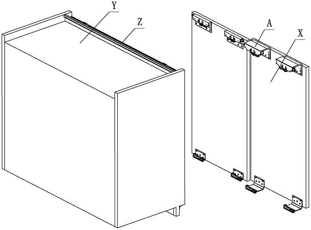
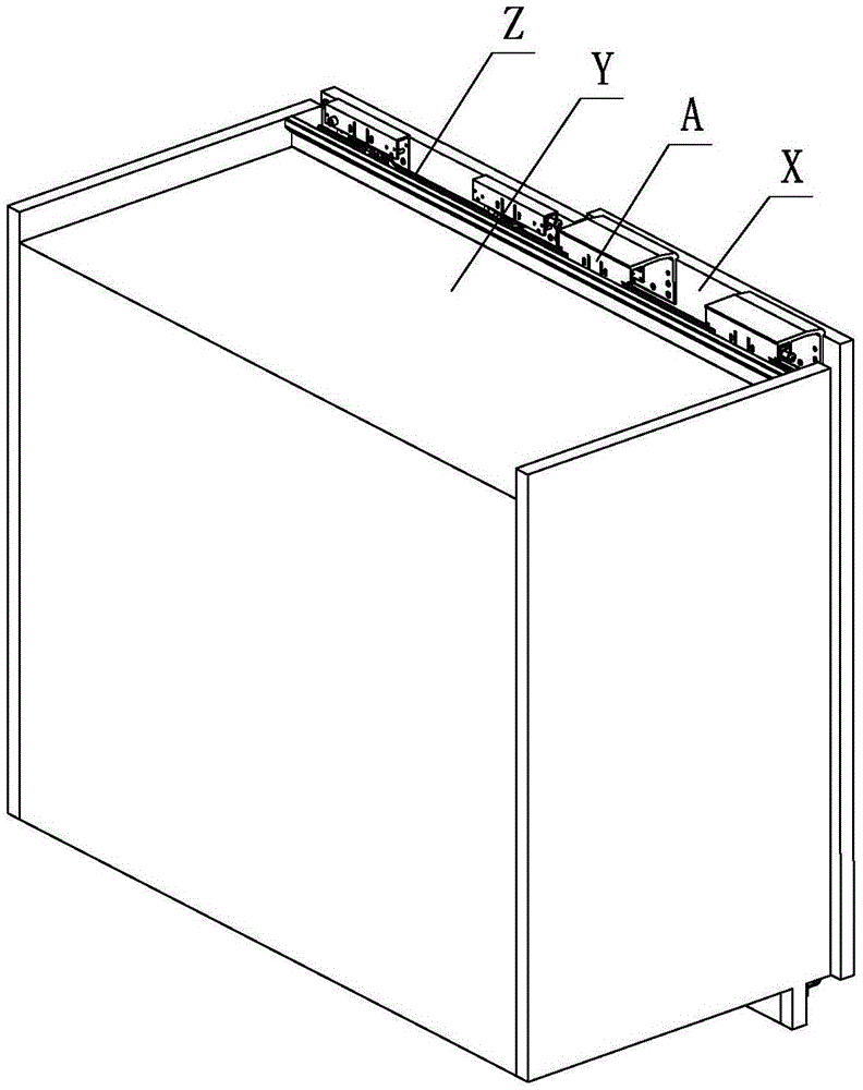
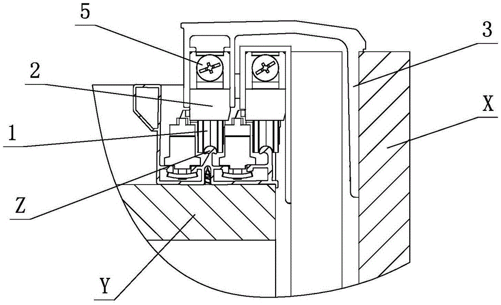
[0032] see Figure 1-Figure 7 The balance bearing adjustment mechanism of the furniture sliding door includes an adjustment device A, the adjustment device A includes a rotating element 1, a supporting element 2 and a bearing element 3, the rotating element 1 is positioned and rotated on the supporting element 2, and the supporting element 2 is slidably arranged on the bearing On the element 3, the adjusting device A also includes an actuating element 4 and an adjusting element 5, the actuating element 4 is slidably arranged on the bearing element 3, and at least two inclined parts 4.1 are arranged at intervals, and the supporting element 2 is arranged corresponding to the inclined parts 4.1 There are a considerable number of inclined fittings 2.1 through which the actuating element 4 interacts with the inclined fittings 2.1 of the support element 2, and the adjusting element 5 is positioned and rotated on the carrier element 3 and interacts with the actuating element 4; A too...

no. 2 example

[0045] see Figure 8-Figure 10 , the balance bearing adjustment mechanism of the furniture sliding door is different from the first embodiment in that: the adjustment element 5 is an eccentric disk, the bearing element 3 is provided with an assembly hole 3.3 corresponding to the eccentric disk, and the actuating element 4 is provided with a corresponding eccentric disk. The eccentric action part 4.3, one end of the eccentric disk is provided with an adjustment action part 5.1, the middle part is positioned and rotated on the assembly hole 3.3 of the bearing element 3, and the other end is provided with an eccentric part 5.2 which interacts with the eccentric action part 4.3 of the actuating element 4, through the tool Or manually adjust the action part 5.1, the eccentric disk is positioned and rotated, and the actuating element 4 is driven to slide laterally on the carrier element 3 through the interaction between the eccentric part 5.2 and the eccentric action part 4.3, and th...


PUM


Abstract

The invention provides a balanced bearing adjustment mechanism for a sliding door of furniture. The balanced bearing adjustment mechanism for the sliding door of the furniture comprises an adjustment device. The adjustment device comprises a rotating element, a supporting element, a bearing element, an actuating element and an adjustment element, wherein the rotating element is rotatably positioned on the supporting element; the supporting element is slidably arranged on the bearing element; the actuating element is slidably arranged on the bearing element, and at least two oblique parts are arranged on the actuating element in a spaced mode; the supporting element is provided with oblique matching parts corresponding to the oblique parts, and the number of the oblique matching parts is the same as the number of the oblique parts; the actuating element interacts with the oblique matching parts of the supporting element through the oblique parts; the adjustment element is rotatably positioned on the bearing element and interacts with the actuating element; and by applying action on an adjustment functional part of the adjustment element through a tool or manually, the adjustment element rotates in a positioned mode and sequentially drives the actuating element, the supporting element and the rotating element to move relative to the bearing element, and thus adjustment of the relative positions of the rotating element and the bearing element is achieved. Through the structural improvement, the practicability is high.

Description

technical field [0001] The invention relates to a furniture sliding door, in particular to a balance bearing adjustment mechanism for a furniture sliding door. Background technique [0002] The Chinese patent literature number is CN204238725U, which discloses a sliding door guide wheel device on April 1, 2015, which includes a base plate, a support plate, a spring, a bolt, a first guide wheel, a second guide wheel, and a limit pin. The first guide wheel and the second guide wheel are arranged side by side on the support plate; the support plate is provided with a through hole, the base plate is provided with a threaded hole, and one end of the spring outer ring is fixed on the right end of the base plate; the nut end of the bolt is fixed to the support plate. The threaded end passes through the through hole and the inner ring of the spring to be threaded with the threaded hole in turn, and one end of the inner ring of the spring is located between the bolt and the right end ...

Claims


Application Information

Patent Timeline
IPC IPC(8): E05D13/00E05D15/06E05F5/06
CPCE05D13/00E05D15/0634E05F5/06E05Y2900/20
Inventor 伍志勇
Owner 伍志勇
Why Eureka
Try Eureka