A cascaded refrigeration cycle system coupled with an ejector

A cycle system and ejector technology, applied in the field of cascade refrigeration cycle systems, can solve the problems of reducing refrigeration capacity, waste, and increasing power consumption of high-temperature stage compressors, so as to improve the heat transfer coefficient, the refrigeration coefficient, and the heat transfer coefficient. The effect of thermal capacity

Active Publication Date: 2018-05-15
SOUTHEAST UNIV
View PDF6 Cites 0 Cited by
  • Summary
  • Abstract
  • Description
  • Claims
  • Application Information

AI Technical Summary

Problems solved by technology

Considering the heat transfer temperature difference in the condensing evaporator, the evaporation temperature of the high-temperature stage is about -15°C, so there is a large temperature difference between the evaporator of the high-temperature stage refrigeration cycle and the exhaust gas of the low-temperature stage compressor, which will cause Serious irreversible loss and waste of cooling capacity in the heat exchange process of the evaporator
At the same time, in the high-temperature refrigeration cycle, the liquid refrigerant will also produce flash vapor after throttling. After this part of flash vapor enters the condensing evaporator, not only will it not generate cold energy in the condensing evaporator, but will also occupy the condensing evaporator for heat exchange. The area affects the evaporation of liquid refrigerant, thereby reducing the heat transfer efficiency of the condensing evaporator and reducing the cooling capacity
Not only that, this part of the flash gas that does not produce cooling capacity will be sucked by the high-temperature compressor and compressed to the condensation pressure after passing through the condensing evaporator, which will increase the power consumption of the high-temperature compressor

Method used


Image

  • A cascaded refrigeration cycle system coupled with an ejector
  • A cascaded refrigeration cycle system coupled with an ejector

Examples


Embodiment Construction

[0015] The present invention will be further described below in conjunction with embodiment and accompanying drawing.

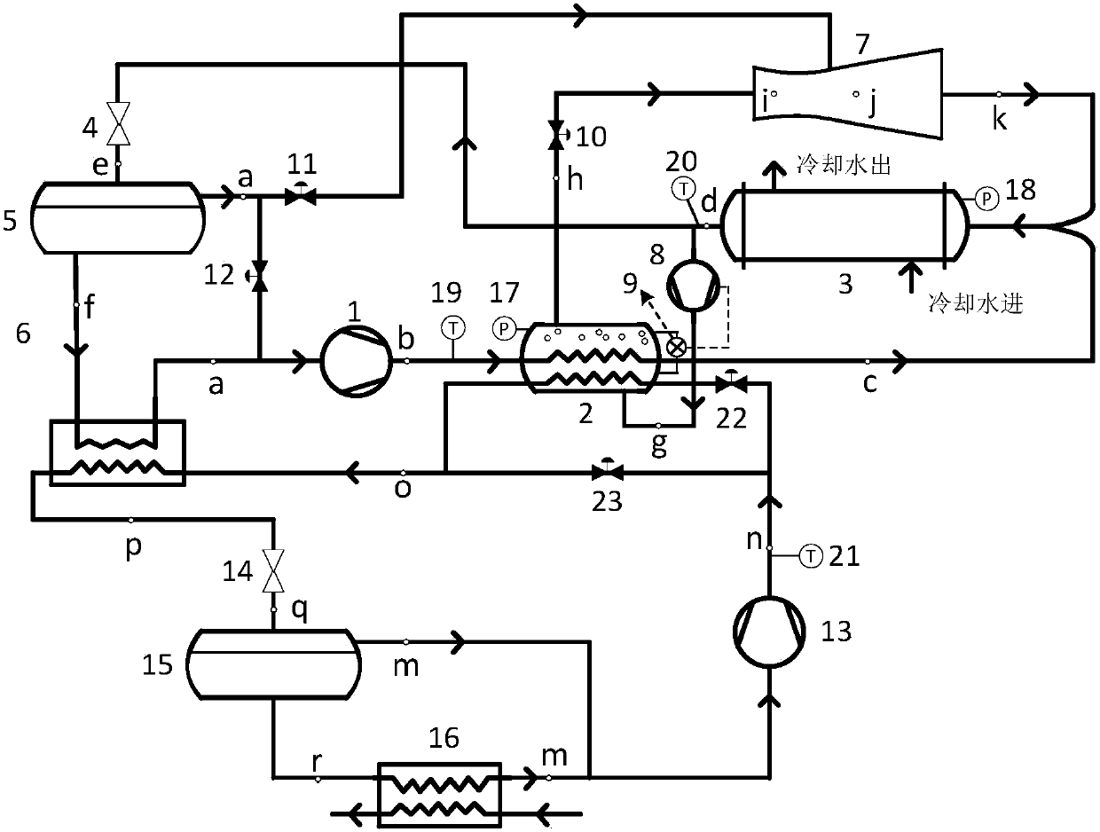
[0016] Such as figure 1 As shown, the cascade refrigeration cycle system that utilizes the exhaust sensible heat of the refrigeration compressor and the coupling of the ejector includes a high-temperature stage compressor, a low-temperature stage compressor, a three-channel generator, a condenser, and a condensation evaporator , throttle valve, gas-liquid separator, evaporator, ejector, liquid booster pump, liquid level controller, solenoid valve, pressure sensor, temperature sensor, etc.

[0017] Its refrigeration cycle method is:

[0018] The saturated liquid refrigerant condensed by the condenser is divided into two paths, one path passes through the throttle valve to reduce temperature and pressure, and the other path passes through the liquid booster pump to pressurize and enter the three-channel generator. The level controls the start and stop of the ...


PUM


Abstract

The invention discloses a cascaded refrigeration cycle system coupled with an ejector. In the system, the superheated steam discharged from the high and low temperature stage compressor will be heated and vaporized and then boosted by a booster pump to the high temperature stage supercooled liquid refrigeration under the generation pressure. The saturated steam generated is used as the working steam of the refrigerant flash gas separated by the gas-liquid separator after the ejector injects the high-temperature stage throttling. Since the sensible heat of the superheated gas discharged from the low-temperature stage compressor is utilized in the three-channel generator, the load of the condensing evaporator is effectively reduced, that is, the cooling capacity of the high-temperature stage refrigeration cycle is reduced. Under the premise of the same cooling capacity of the low-temperature stage, the refrigeration load of the high-temperature stage cycle and the power consumption of the compressor will be reduced, and the COP of the entire cascade refrigeration cycle will be improved. A preliminary estimate of the cascade refrigeration system composed of NH3 and CO2 can be obtained: the refrigeration coefficient of this system will be increased by about 10% compared with the traditional cascade refrigeration system.

Description

technical field [0001] The invention belongs to the field of refrigeration cycles, and relates to a cascaded refrigeration cycle system coupled with an ejector. Background technique [0002] In the traditional cascade refrigeration cycle, the exhaust gas of the low-temperature stage compressor with a relatively high degree of superheat directly enters the condensing evaporator and must first be cooled and then condensed into a saturated liquid or a liquid with a certain degree of supercooling. The level of cooling and condensation load directly affects the cooling capacity of the high-temperature refrigeration cycle. Take NH 3 and CO 2 Take the cascade refrigeration system as an example. When the evaporation temperature of the low-temperature stage is -50°C and the condensation temperature is -10°C, the exhaust gas of the low-temperature stage compressor is CO 2 The temperature is about 60°C. Considering the heat transfer temperature difference in the condensing evaporat...

Claims


Application Information

Patent Timeline
Patent Type & Authority Patents(China)
IPC IPC(8): F25B7/00F25B25/00F25B41/00F25B41/40
CPCF25B7/00F25B25/005F25B41/00
Inventor 江巍雪杜垲李彦军
Owner SOUTHEAST UNIV
Why Eureka
Try Eureka