Method of carrying out the final stage of bottom yarn feeding with winding station and automatic winder

An automatic winder and bottom yarn technology, which is applied in the directions of transportation and packaging, thin material handling, and conveying filamentous materials, etc., can solve the problem that the bottom yarn cannot be obtained by operators or maintenance units.

Inactive Publication Date: 2018-12-14
SAURER GERMANY GMBH & CO KG
View PDF7 Cites 0 Cited by
  • Summary
  • Abstract
  • Description
  • Claims
  • Application Information

AI Technical Summary

Problems solved by technology

However, since the yarn guide channel must be sealed in this area for suction, i.e. closed, the ground yarn cannot be accessed there by the operator or the maintenance crew, but another conveying mechanism is required for the final stage of the ground yarn feeding

Method used


Image

  • Method of carrying out the final stage of bottom yarn feeding with winding station and automatic winder
  • Method of carrying out the final stage of bottom yarn feeding with winding station and automatic winder
  • Method of carrying out the final stage of bottom yarn feeding with winding station and automatic winder

Examples


Embodiment Construction

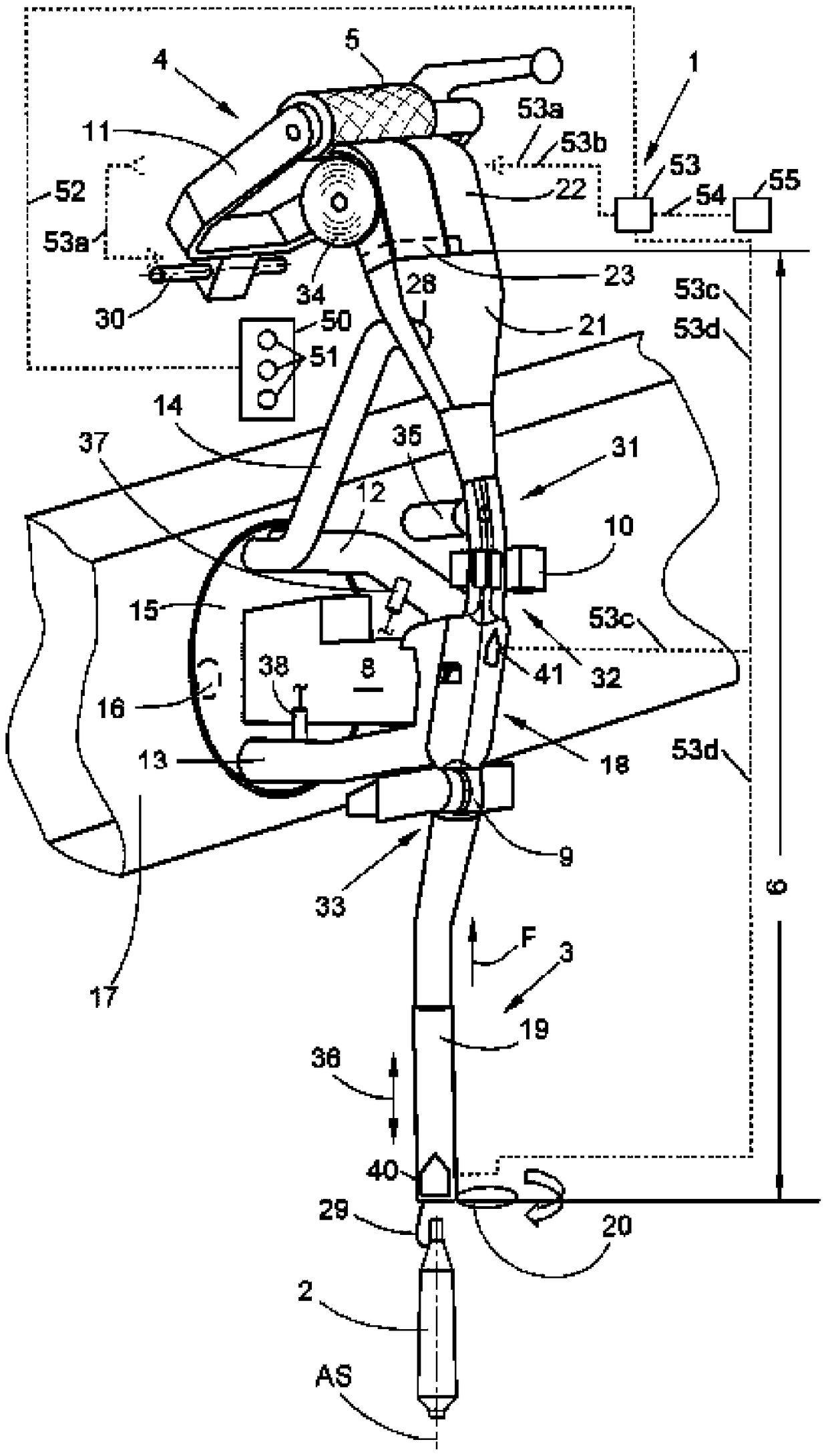
[0029] Basically obtained from DE102010049515A1 (and numbered there as well) figure 1 A three-dimensional view schematically shows the winding position 1 of the automatic winder, which has a multi-part yarn guide channel 6 surrounding the yarn travel path, and the yarn guide channel can withstand negative pressure and compressed air as required. The components that are important for the understanding of the present invention and their working methods are described below, and other details on the working methods of the winding position 1 can also be found in DE102010049515A1.

[0030] The bottom yarn 29 from the unwinding bobbin 2 in the unwinding position AS is guided in the yarn direction F through the yarn guide channel 6 and is rewound onto the winding bobbin 5 in the form of a cross-winding bobbin. The winding bobbin 5 is held in the creel 11 pivotable about the pivot shaft 30 and is driven by the friction roller 34. The friction roller 34 also serves as a grooved cylinder for...


PUM


Abstract

The invention relates to pneumatic closure of ground yarn transportation into winding bobbin, and a winding unit and an automatic winder. Specifically, the invention relates to a method for carrying out the final phase of the ground yarn feeding, i.e., for transporting a ground yarn (29) from an area which is near an empty tube of a winding bobbin (5) of a winding unit (1) of an automatic winder and where the ground yarn cannot be unceasingly and directly processed to an area where that the ground yarn (29) is connected with the empty tube of the winding bobbin (5) is achieved directly by an operator or an automatic device such as a service unit of the automatic winder. The method is characterized in that the final phase of the ground yarn feeding is achieved by the rotation of a friction roller (34) which can be brought in frictional engagement with the winding bobbin (5) or by the rotation of the winding bobbin (5) or by the rotation of these two elements. However, the invention also relates to a winding unit (1) of an automatic winder or an automatic winder having a winding unit (1), characterized in that a control of the winding unit (1) or the automatic winder is configured to carry out such a method.

Description

Technical field [0001] The present invention relates to a winding position for rewinding a relatively small package of spinning bobbin or, in general, an unwinding bobbin into a large package, an automatic winder including the winding position, and a bottom The yarn is transported from the unwinding bobbin to the final stage near the newly inserted empty bobbin of the winding bobbin, where the bottom yarn can then be received to be fixed on the empty bobbin. Background technique [0002] In the so-called batch replacement, that is, when changing the yarn type, not only the empty bobbin for the new winding bobbin must be used, but also there is no previous winding near the empty bobbin due to the yarn change. The bottom yarn of the process is available. Therefore, the bottom yarn must first be sent there from the newly unwound bobbin to be unwound. It is also called bottom yarn feeding. The necessity of doing so may arise in some other cases besides batch replacement, for examp...

Claims


Application Information

Patent Timeline
Patent Type & Authority Patents(China)
IPC IPC(8): B65H51/04B65H51/30B65H65/00B65H54/42B65H75/28
CPCB65H65/00B65H51/16B65H54/72B65H57/12B65H67/083B65H2701/31
Inventor D·德肯弗朗茨-约瑟夫·弗拉姆
Owner SAURER GERMANY GMBH & CO KG
Why Eureka
Try Eureka