X-ray apparatus with improved patient access

a technology of x-ray equipment and patient access, which is applied in the field of x-ray equipment, can solve the problems of limiting the use of x-ray devices in medical and dental applications, affecting patient anxiety and distraction, and affecting patient access to and from the patient positioning area

Inactive Publication Date: 2001-01-02
MORITA MFG CO LTD
View PDF15 Cites 64 Cited by
  • Summary
  • Abstract
  • Description
  • Claims
  • Application Information

AI Technical Summary

Problems solved by technology

X-ray devices commonly used in medical and dental applications are limited by their ability to accommodate patients and operators while carrying out technical operations.
However, achieving this in a physically confined space can lead to other problems.
Components of the apparatus may impede patient access to and from the patient positioning area and may also obscure a necessary view of the patient by an operator of the apparatus.
The patient's ability to vi

Method used


Image

  • X-ray apparatus with improved patient access
  • X-ray apparatus with improved patient access
  • X-ray apparatus with improved patient access

Examples


first embodiment

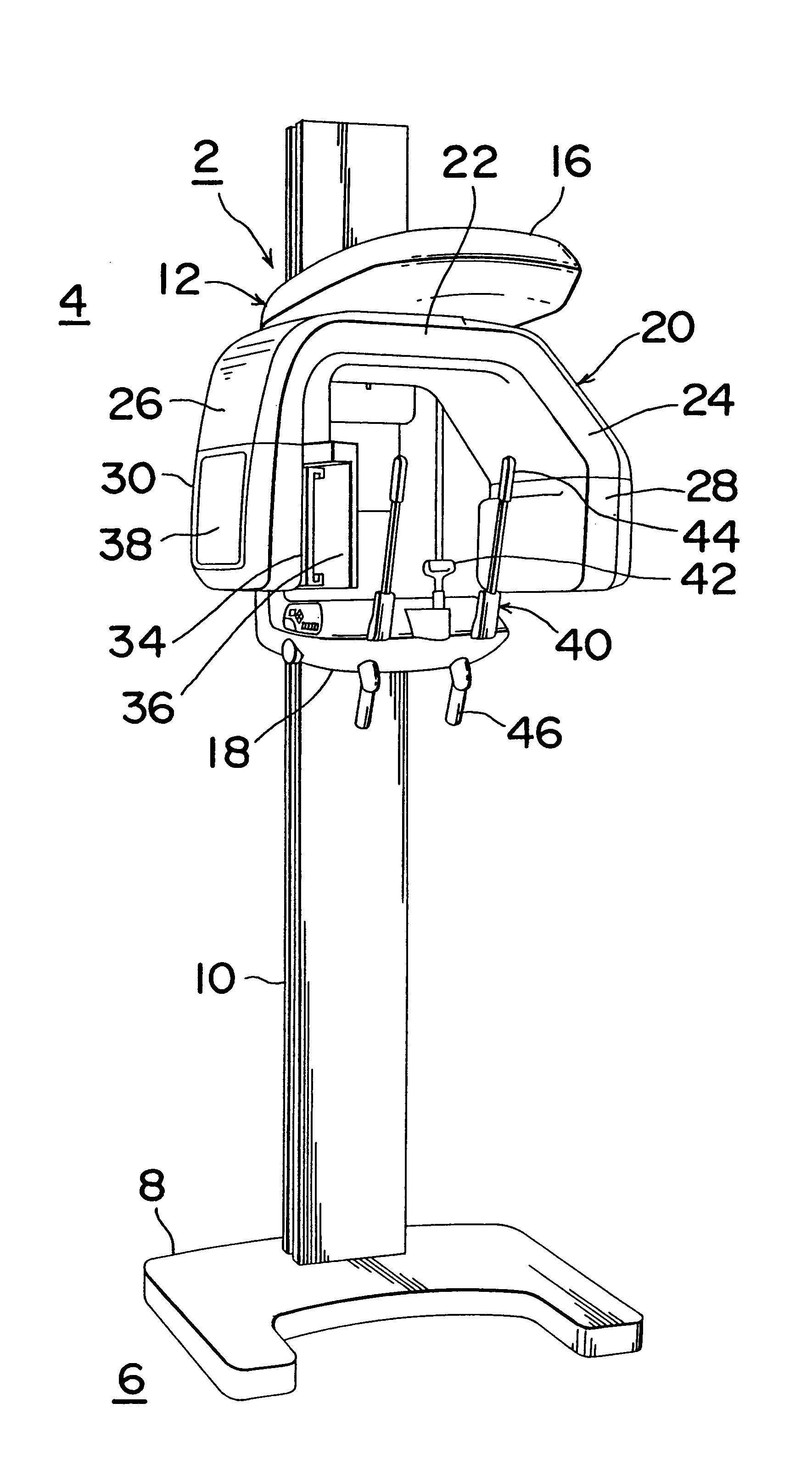
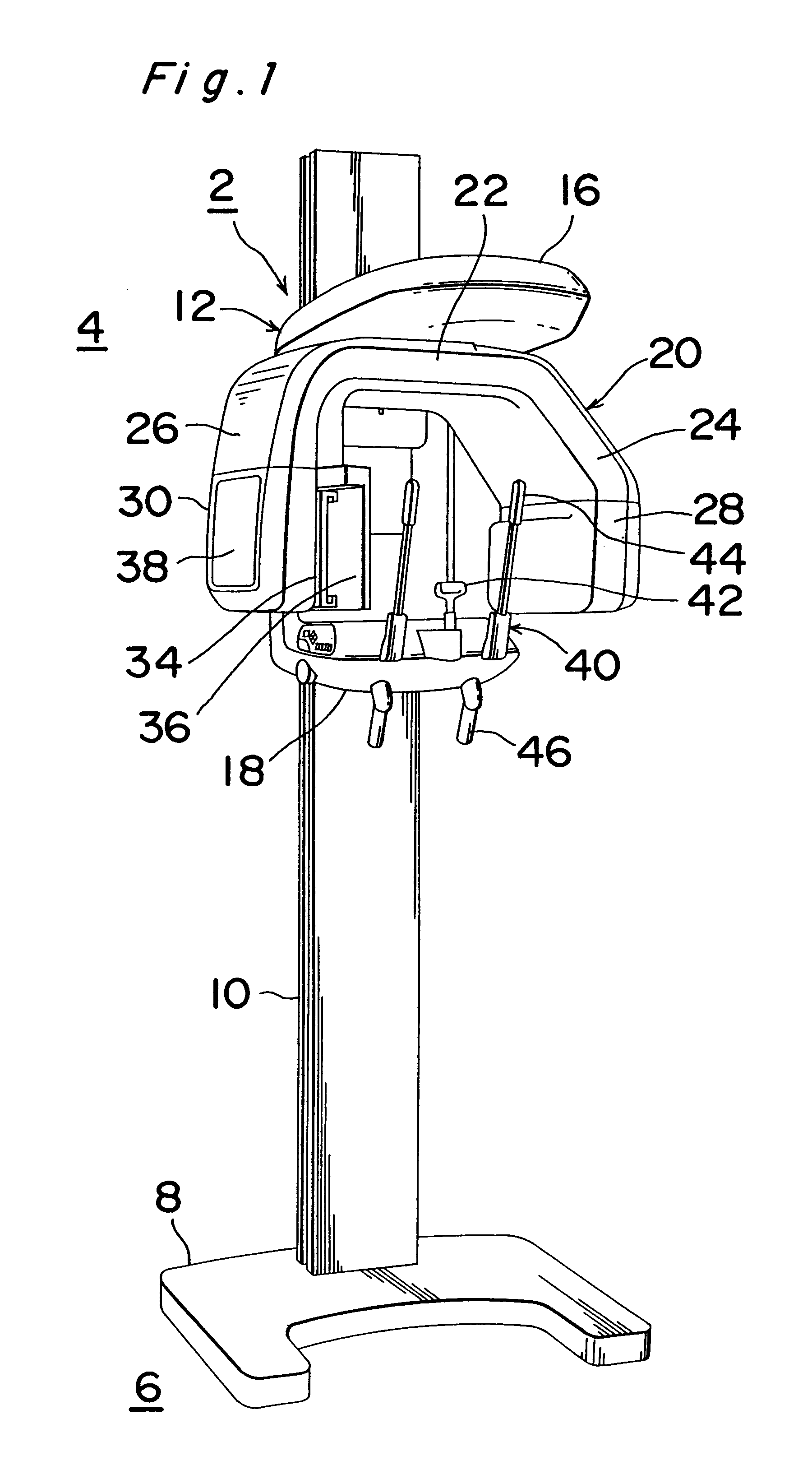
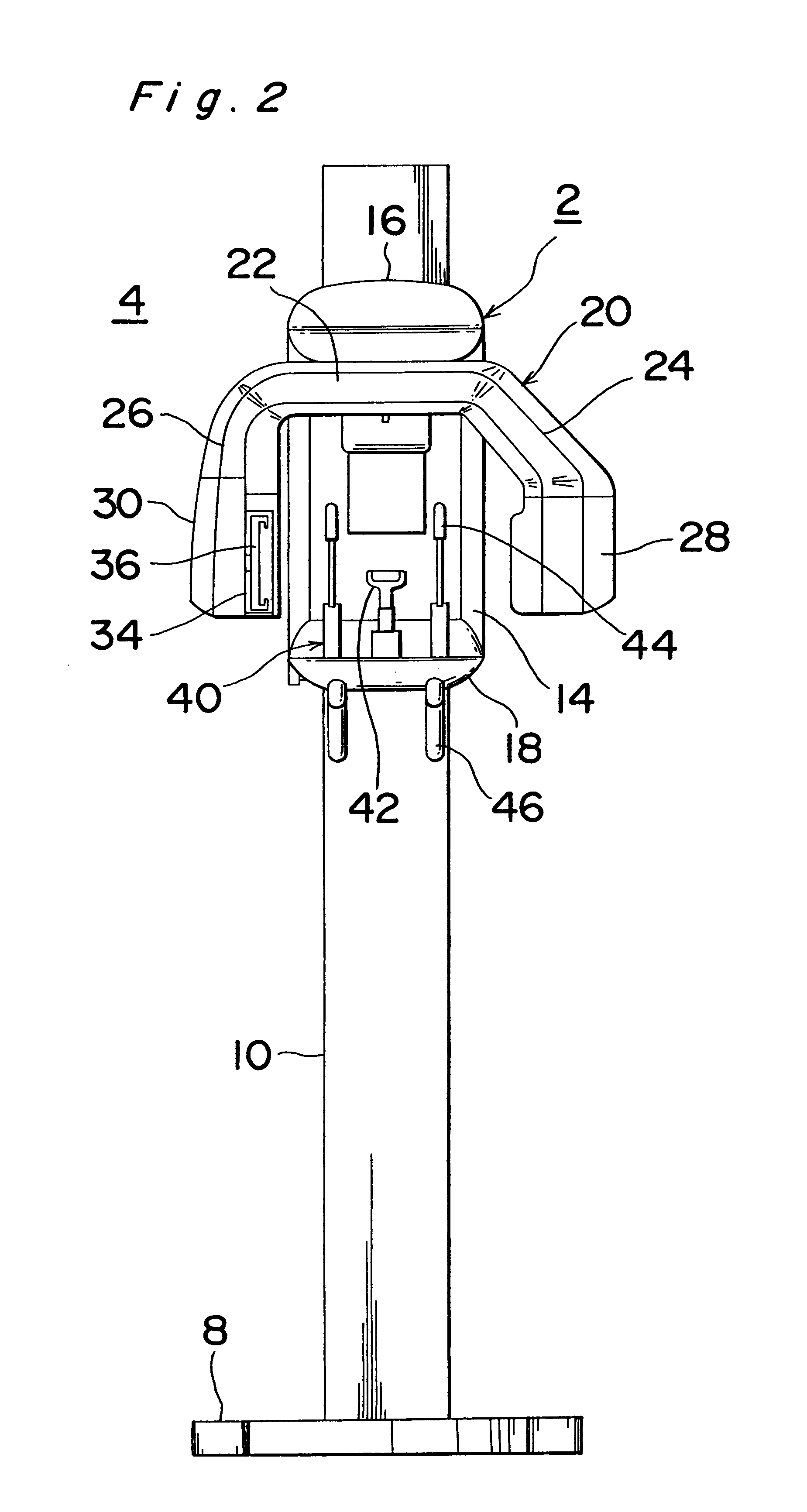
Referring to the drawings, particularly in FIGS. 1 to 4, there is shown a dental X-ray apparatus of the present invention, generally indicated by reference numeral 2. The X-ray device 2, which is typically installed in a chamber 4 suitably constructed for an X-ray tomography, includes a base plate 8 fixed on a floor 6 of the chamber 4, and a column 10 fixed at a bottom portion thereof on the base plate 8 and extended substantially vertically. The column 10 supports an elevation unit (first frame) 12 capable of moving up and down along the column 10. The elevation unit 12 integrally includes a substantially vertical portion 14 extending along the column 10, an upper portion (support) 16 extending substantially horizontally from an upper end of the vertical portion 14, and a lower portion 18 extending substantially horizontally and parallel to the upper portion 16.

Provided between the upper and lower portions 16 and 18 of the elevation unit 12 is a gate-like revolving arm (second revo...

second embodiment

FIG. 23 shows a dental X-ray apparatus of the present invention, generally indicated by reference numeral 190. In this X-ray apparatus, an upper portion 192 of an elevation unit integrally includes a first upper portion 196 extending from a column 194 in the Y-direction and a second upper portion 198 extended from an distal end of the first upper portion 196 and angled therewith about 30 to 60 degrees, preferably about 45 degrees. Likewise, a lower portion 200 of the elevation unit may be angled as necessary.

With this arrangement, as illustrated, the patient can be oriented toward that angled direction, allowing the operator OP to look at the patient more easily.

Also in this embodiment, the use of the displacing mechanism 202 of the upper portion 192 of elevation unit and, if necessary, the second displacing mechanism of the revolving arm 20 will ease the patient's approach to the positioning station and / or the operator's view of the patient.

third embodiment

FIGS. 24 and 25 illustrate an X-ray apparatus according to the present invention additionally having a cephalostat generally indicated by reference numeral 212. The X-ray apparatus, except for the cephalostat, may have the same construction as that described above. The cephalostat 212 has a frame 214 including a cassette holder 216 for holding a cassette 215 and a positioning device 218 for holding and positioning the head of patient. The cassette 215 may include a X-ray receiving film or X-ray fluorescent sheet, or a MOS sensor. Further, the cephalostat 212 includes an X-revolving arm 220 which horizontally extends in the X-direction from a rear portion of the elevation unit 12 of the X-ray device 210 and a Y-revolving arm 222 which extends from a distal end of the X-revolving arm 220 in the Y-direction. In addition, the frame 214 is supported at the distal end of the Y-revolving arm 222. In the cephalogram using the X-ray device 210 equipped with the cephalostat 212, the revolving...


PUM


Abstract

An X-ray device for generating a panoramic tomogram is designed so that a revolving arm can move between a first position, where an X-ray generator and an X-ray receiver that are both supported by the revolving arm oppose each other through the head of a patient positioned in a patient positioning station, and a second position, where an operator of the X-ray device can look at the patient's head from a side view, thereby allowing the operator to properly position the patient in the patient positioning station. The incorporation of a second X-ray receiver additionally allows for the generation of a cephalogram. The incorporation of a blind prevents the patient from visually or physically interacting with selected components of the apparatus.

Description

1. Field of InventionThe present invention relates to an X-ray apparatus and more particularly to dental X-ray apparatus for generating a panoramic tomogram.2. Description of Related ArtX-ray devices commonly used in medical and dental applications are limited by their ability to accommodate patients and operators while carrying out technical operations. On one hand, the apparatus must be capable of carrying out detailed translations and rotations of the X-ray source and receiver. However, achieving this in a physically confined space can lead to other problems. Components of the apparatus may impede patient access to and from the patient positioning area and may also obscure a necessary view of the patient by an operator of the apparatus. The patient's ability to view components of the apparatus in operation can lead to patient anxiety and distraction. Furthermore, the patient's ability to interact physically with components of the apparatus can endanger both the patient and the ap...

Claims


Application Information

Patent Timeline
IPC IPC(8): A61B6/14
CPCA61B6/14
Inventor YOSHIMURA, TAKAHIROYOSHIDA, MASANOBUOTSUKA, MASANORI
Owner MORITA MFG CO LTD
Why Eureka
Try Eureka