
System and method for performing distributed multipoint video conferencing

a multi-point video and video conferencing technology, applied in the field of communication, can solve the problems of network architecture and the field of video conferencing have grown increasingly complex in the communications environment, and the challenge is significant for network operators, component manufacturers, and system designers, so as to reduce the disadvantages and problems associated

Active Publication Date: 2007-03-22
CISCO TECH INC
View PDF31 Cites 66 Cited by
  • Summary
  • Abstract
  • Description
  • Claims
  • Application Information

AI Technical Summary

Benefits of technology

[0005] From the foregoing, it may be appreciated by those skilled in the art that a need has arisen for an improved communications approach that provides for more appropriate data-routing procedures to achieve optimal data management in a video conferencing environment. In accordance with one embodiment of the present invention, a system and a method for performing distributed multipoint video conferencing is provided that greatly reduces disadvantages and problems associated with conventional information distribution techniques.
[0007] According to an embodiment of the present invention, an apparatus for performing video conferencing is provided that includes an I-frame injector element operable to intercept I-frame requests from one or more end points and to attempt to service the I-frame requests such that at least a portion of the requests are prevented from propagating back to an originating sender.
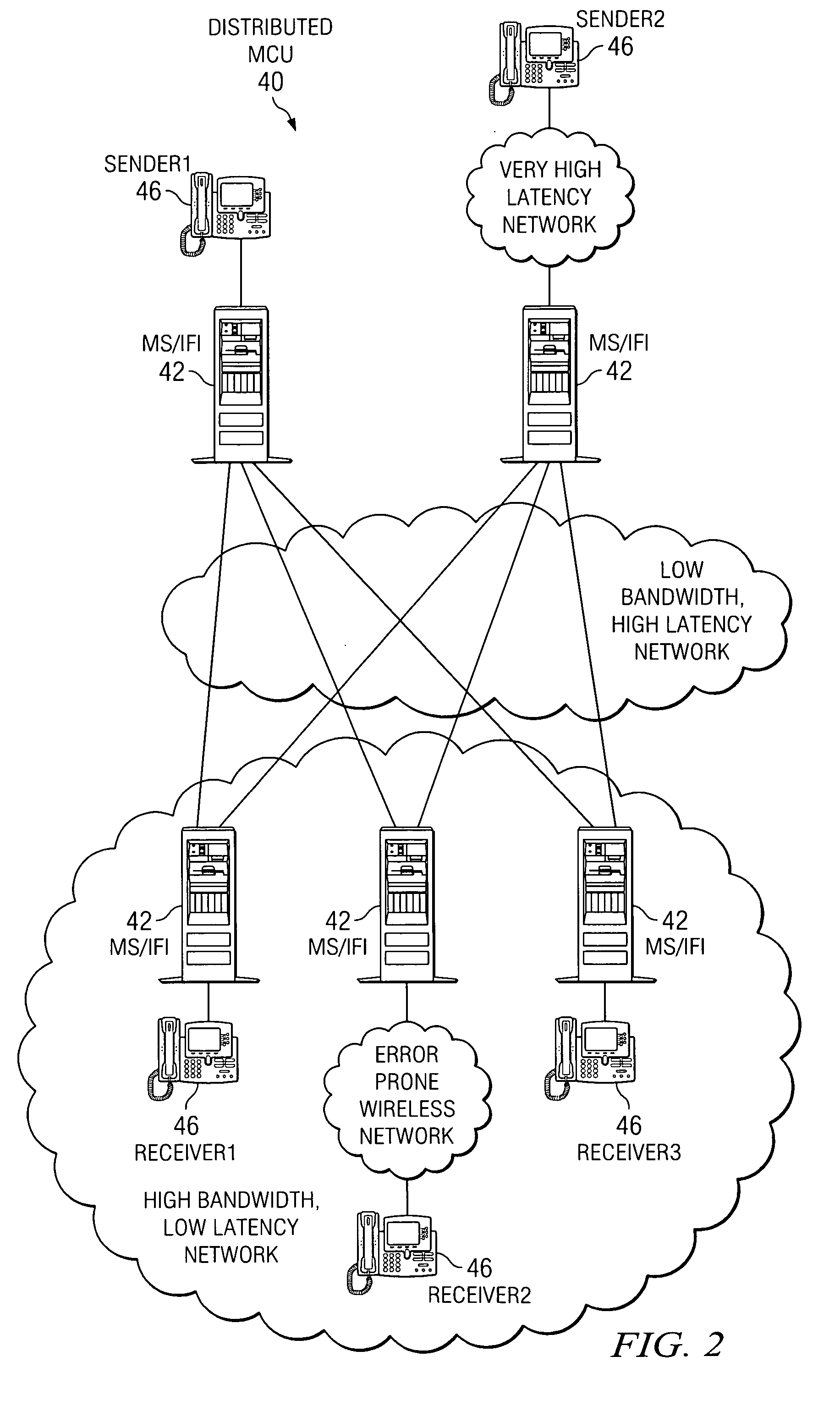
[0009] Certain embodiments of the present invention may provide a number of technical advantages. For example, according to one embodiment of the present invention, a video conferencing architecture is provided that allows for enhanced performance. In the distributed MCU architecture, the I-frame injector can be situated on media switches to intercept fast video update (FVU) requests from endpoints in the subnet. The FVU requests are serviced by the I-frame injector, rather than being forwarded to the originating sender. As a result, endpoints receive I-frames faster. In addition, the I-frame injector reduces the average bandwidth over the core of the network (e.g. the wide area network (WAN)) by reducing the number of I-frames that must be issued by the originating sender. Also, the I-frame injector prevents higher bandwidth I-frames from flooding all endpoints in the distributed MCU mesh because the I-frames are limited to the subnet of the media switch. This feature is especially helpful if the subnet at the edge is a suspect wireless link that could potentially be the cause of an I-frame storm.
[0010] Another advantage associated with one embodiment of the present invention is that there may be more bandwidth available on the local subnet than there is on the WAN. As a result, the I-frame injector may be able to send a high-quality I-frame very quickly. This I-frame would be large and, further, could be sent with back-to-back packets. In contrast to this optimal scenario, a sender that is emitting an I-frame for transmission over the WAN may be constrained to a smaller bit-rate and stretch the I-frame out over a longer period of time. This would result in longer delays.

Problems solved by technology

Networking architectures and the field of video conferencing have grown increasingly complex in communications environments.
Accordingly, the ability to provide an effective mechanism to properly direct communications for an end user / end point, or to offer an appropriate protocol that optimizes bandwidth characteristics provides a significant challenge to network operators, component manufacturers, and system designers.

Method used


Image

  • System and method for performing distributed multipoint video conferencing
  • System and method for performing distributed multipoint video conferencing
  • System and method for performing distributed multipoint video conferencing

Examples


Embodiment Construction

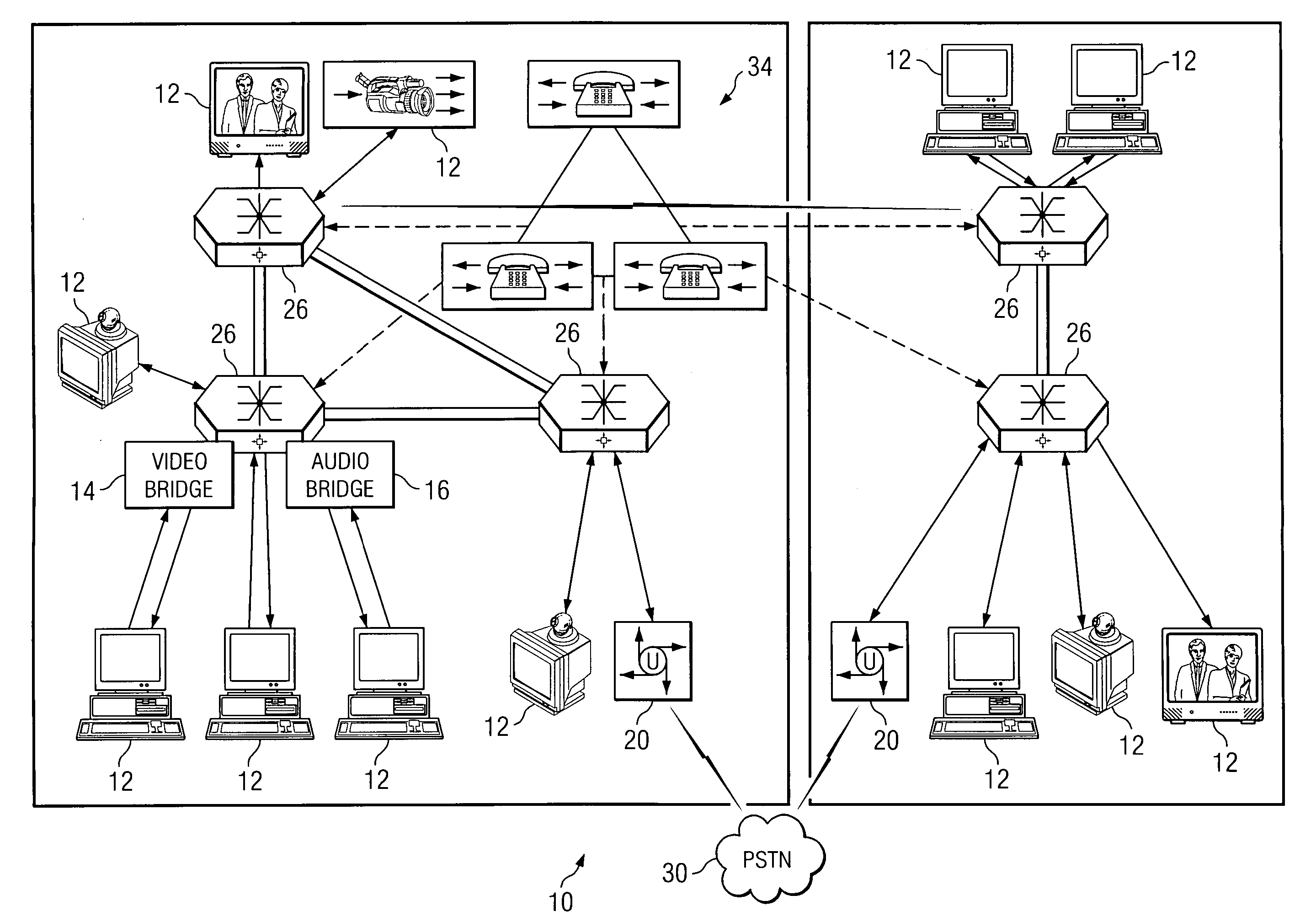
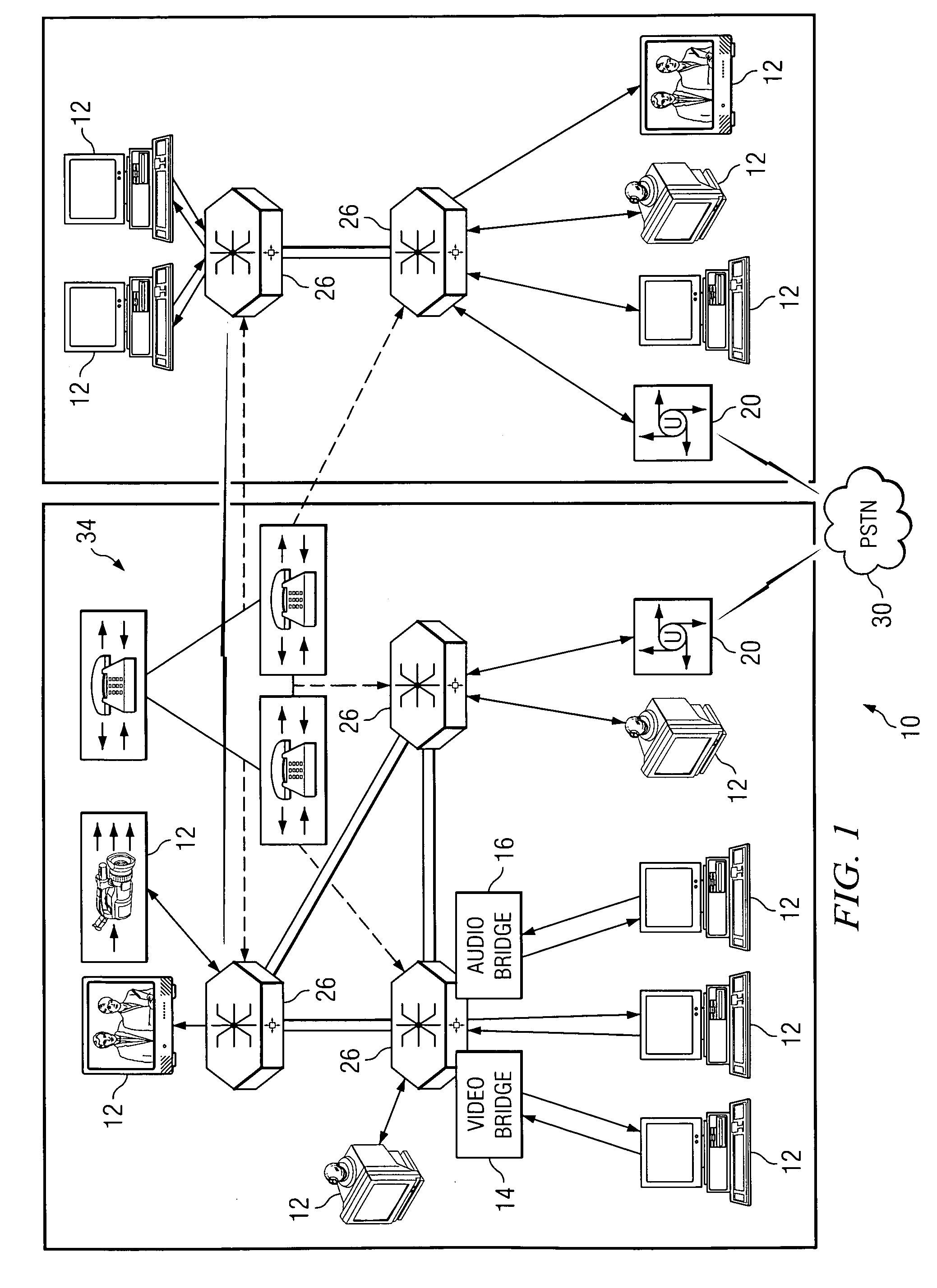
[0018]FIG. 1 is a simplified block diagram of a communication system 10 for communicating data in a network environment. Communication system 10 includes multiple end points 12, which are illustrated in FIG. 1 as representative of various devices and components (e.g. audio internet protocol (IP) phones, video phone appliances, personal computer (PC) based video phones, and streaming clients). Communication system 10 may also include a plurality of gateways 20 that provide connectivity to each other via a public switched telephone network (PSTN) 30. Communication system 10 may also include a plurality of media switches 26 (which may be abbreviated as MS or MSs herein in this document) that may be coupled to each other, gateways 20, and various end points 12. Additionally, communication system 10 may include a set of call agents 34 (e.g. a centralized call manager) that may be coupled to media switches 26. In addition, communication system 10 may include any number of suitable applica...


PUM


Abstract

According to an embodiment of the present invention, an apparatus for performing video conferencing is provided that includes an I-frame injector element operable to intercept I-frame requests from one or more end points and to attempt to service the I-frame requests such that at least a portion of the requests are prevented from propagating back to an originating sender. In more specific embodiments, when a receiver endpoint sends a fast video update (FVU) request upstream, it is intercepted by the I-frame injector element and rather than passing the FVU request to the sender the I-frame injector element replaces a next P-frame from the sender with an I-frame, whereby the I-frame is constructed so that when decoded, it matches the P-frame that it replaced. In still more detailed embodiments, the I-frame injector element operates in one of three modes that are associated with bandwidth parameters.

Description

TECHNICAL FIELD OF THE INVENTION [0001] This invention relates in general to the field of communications and, more particularly, to a system and a method for performing distributed multipoint video conferencing. BACKGROUND OF THE INVENTION [0002] Networking architectures and the field of video conferencing have grown increasingly complex in communications environments. In addition, the augmentation of clients or end users wishing to communicate in such environments has caused many networking configurations and systems to respond by adding elements to accommodate the increase in networking traffic. Communication tunnels or links may be used in order to establish a communication flow, whereby an end user or an object may initiate a video or an audio session to facilitate a particular call or conference. Selected locations within the communication architecture may be accessed or designated to conduct the communication session. The selected location or network point may then provide a p...

Claims


Application Information

Patent Timeline
Patent Type & Authority Applications(United States)
IPC IPC(8): H04M3/42
CPCH04N7/15H04N7/152
Inventor BAIRD, RANDALL B.FIRESTONE, SCOTT S.SURAZSKI, LUKE K.WU, DUANPEI
Owner CISCO TECH INC
Learn More