LED lamp

A technology of LED lamps and LED tubes, which is applied in the field of lighting, can solve problems such as limited light-emitting area, and achieve the effects of saving costs and resources, avoiding glare, and improving light control efficiency

Inactive Publication Date: 2016-06-22
李忠凯
View PDF7 Cites 1 Cited by
  • Summary
  • Abstract
  • Description
  • Claims
  • Application Information

AI Technical Summary

Problems solved by technology

Obviously, the light-emitting range of the LED light strip 14 is limited by the planar design of the LED light tube, which limits the light-emitting area.
[0003] Moreover, the setting of the prior art cannot avoid the glare caused by the direct light of the LED strip

Method used


Image

  • LED lamp
  • LED lamp
  • LED lamp

Examples


Embodiment 1

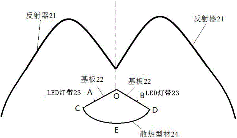
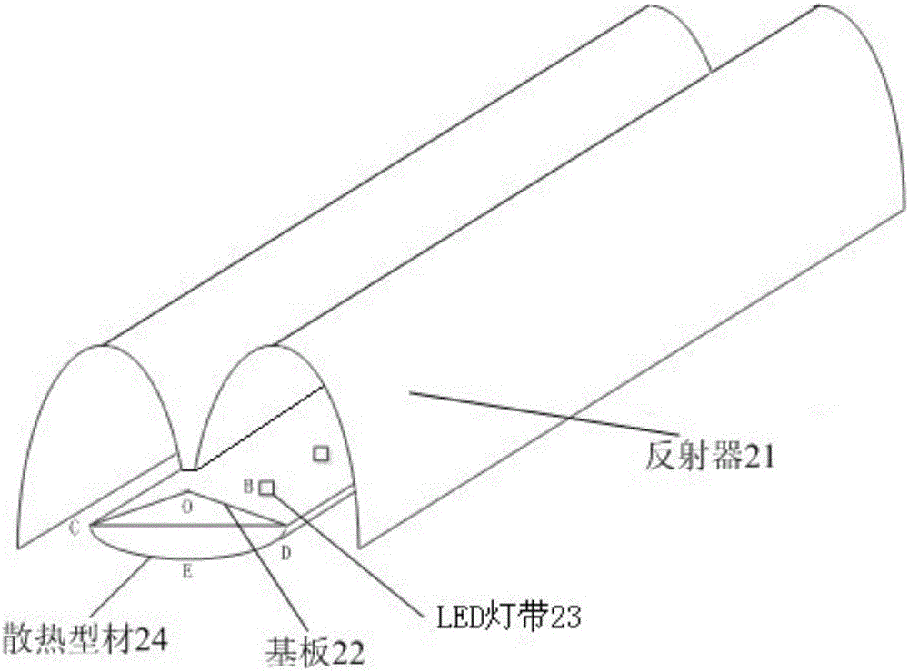
[0041] Such as Figure 2-7 As shown, according to the embodiment of the present application, an LED lamp is provided, including: an LED lamp housing 25 , an LED lamp tube and a reflector 21 .

[0042] LED light tube

[0043] Such as Figure 2-7 As shown, the LED light tube further includes: a substrate 22 represented by CO and DO, an LED light strip 23 represented by points A and B, and the substrate 22 has along the extending direction of the LED light tube An extended structure (i.e., image 3 The part of COD along the extension direction of reflector 21), the extension structure has a triangular or V-shaped protrusion (the part shown by point COD), the bottom surface of the extension structure has a planar structure, and the LED The light strip 23 is attached to the slopes on both sides of the protrusion (that is, the slope shown by CO and the slope shown by DO) to form two light-emitting surfaces, and the light-emitting surface formed by the combination of the two lig...

Embodiment 2

[0055] Such as Figure 8-13 As shown, the present application proposes another LED lamp, including: an LED lamp housing 45 , an LED lamp tube and a reflector 41 .

[0056] LED light tube

[0057] The LED light tube further includes: a base plate 42 (position between C and D) and an LED strip 43 (position between A and B), the base plate 42 has a planar structure, and the LED strip 43 is fixed on Two sides of the central axis of the substrate 42 along the extension direction of the lamp form two light-emitting surfaces (CO and DO form two light-emitting surfaces). Since the LED light strips of the existing LED light tubes are installed directly perpendicular to the substrate plane, in order to save resources and make the best use of the LED light strip’s luminous effect, the LED light strips are arranged on two light-emitting surfaces, that is, the LED The light strips are fixed on both sides of the central axis of the substrate along the extension direction of the lamp so ...


PUM


Abstract

The invention provides an LED lamp. The LED lamp comprises a lamp tube and a reflector; the lamp tube comprises a substrate and a lamp strip; the substrate has an extending structure in the extending direction of the lamp tube and is provided with a protrusion with the triangular section or V-shaped section, a plane structure is arranged on the bottom face of the substrate, the lamp strip is attached to slopes on the two sides of the protrusion so as to form two light-emitting faces, and the combined light-emitting angle is larger than 180 degrees; the reflector has an extending structure in the extending direction of the lamp tube, the cross sections of the reflector are two domes which are connected side by side, and an opening is formed in the bottom end of the reflector; the reflector is connected with the protrusion of the substrate through the connecting end of the domes, openings of the domes face the light-emitting faces, and are each located in the surrounding of one dome, and the opening areas of the domes are larger than the areas of the light-emitting faces; and light of each light-emitting face is shot to the inner wall of the corresponding dome, the light is reflected through the inner walls of the domes and shot out through parts, not shielded by the light-emitting faces, in the openings of the domes, the protrusion is provided with a hollow structure to form a ventilation and heat dissipation channel, and the reflector is fixed to the top point position of the protrusion of the substrate through the connecting end of the domes.

Description

technical field [0001] The present application relates to the lighting field, in particular to an LED lamp. Background technique [0002] Existing LED luminaires such as figure 1 As shown, it includes: a substrate 11 , a heat sink 12 , and an LED strip 14 . Wherein, the LED strip 14 (at the position of point O) is placed on the substrate. The discharge of the LED strip 14 is sequentially discharged along with the extension structure of the substrate 11 (the position between point C and point D), and the LED strip 14 is arranged in a 180-degree plane to discharge, so the released light angle is the largest Form 180 degrees. Apparently, the light-emitting range of the LED light strip 14 is limited by the planar design of the LED light tube, which limits the light-emitting area. [0003] Moreover, the setting of the prior art cannot avoid the glare caused by the direct light of the LED strip. Then, in order to avoid glare, a corresponding lampshade 13 is placed on the LED ...

Claims


Application Information

Patent Timeline
Patent Type & Authority Applications(China)
IPC IPC(8): F21K9/20F21K9/68F21V19/00F21V29/83F21V15/01F21V29/503F21Y115/10F21Y103/10F21V29/50
CPCF21V15/01F21V19/001F21V29/503F21V29/83F21S4/28F21V7/005F21V7/04F21V17/10F21Y2103/10F21Y2115/10
Inventor 李忠凯
Owner 李忠凯
Why Eureka
Try Eureka