Liquid heating device

A heating device and liquid technology, applied in the direction of fluid heaters, water heaters, heating element shapes, etc., can solve the problems of continuous change and adjustment of water temperature, complex casting aluminum production process, and intermittent water outlet, etc., to reduce power-on preheating The effect of waiting time, avoiding long-term use of leakage, and stabilizing the outlet water temperature

Active Publication Date: 2016-06-29
广西桂仪科技有限公司
View PDF9 Cites 10 Cited by
  • Summary
  • Abstract
  • Description
  • Claims
  • Application Information

AI Technical Summary

Problems solved by technology

Due to the large thermal inertia of aluminum, there will be the following problems: 1. When starting up, it takes a long time for 15 to 30 seconds (seconds) to warm up before the cast aluminum can be heated to the required temperature; In the case of water, the heat generated by the heating resistance wire cannot keep up with the heat absorbed by the liquid in time, which will cause the temperature of the cast aluminum to drop. If the required water temperature cannot drop, you need to continue to wait for heating; 3. If the heater is in standby, you need to Use the control to keep the temperature of the cast aluminum constant, resulting in a waste of energy; 4. The cast aluminum heater with such a high thermal inertia must be preheated to obtain water at a constant temperature. When the water is continuously discharged, the water temperature cannot be kept constant.
Because of the inertia of high heat, it is impossible to realize the continuous change and adjustment of water temperature
At the same time, the production process of cast aluminum is complex, large in size and heavy in weight.
[0004] Based on the above problems, there are some solutions to improve, such as making a plastic liquid flow channel in a stainless ste

Method used


Image

  • Liquid heating device
  • Liquid heating device
  • Liquid heating device

Examples


Embodiment Construction

[0033] The present invention will be further described below in conjunction with accompanying drawing and embodiment:

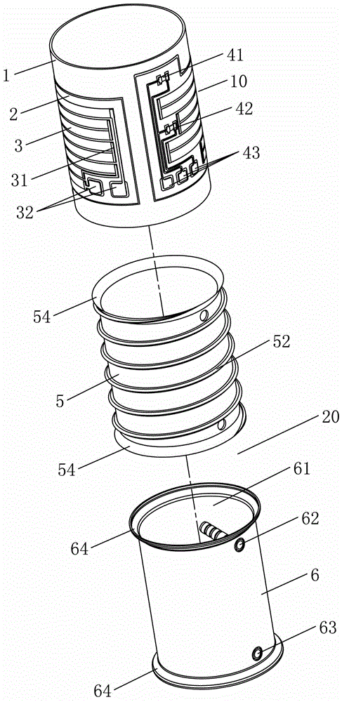
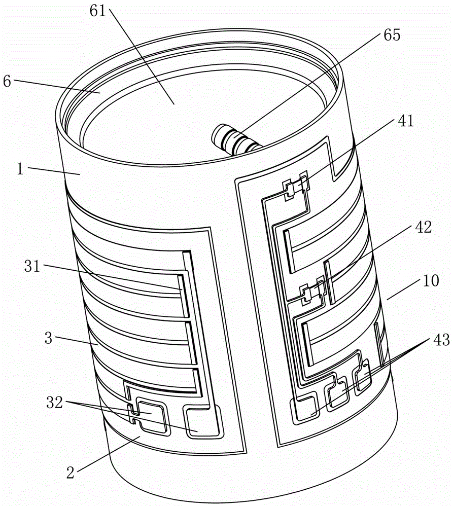
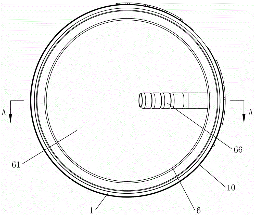
[0034] see Figure 1 to Figure 4As shown, a liquid heating device includes a main body 20 and a heating element 10 respectively in a cylindrical structure. The heating element 10 is set outside the surface of the main body 20. The heating element 10 is composed of an outer tube 1 and a heating element printed on the outer surface of the outer tube 1. Circuit structure, the main body 20 is composed of an inner tube 6 and a silicone sleeve 5, the two ends of the inner tube 6 are respectively sealed and matched with the two ends of the outer tube 1, an inner cavity is formed between the outer tube 1 and the inner tube 6, and the silicone sleeve 5 is set Outside the inner tube 6 and in the closed inner cavity, the outer surface of the silicone sleeve 5 is provided with convex ribs 52, and the ribs 52 are sealed and matched with the inner wall of the outer tube 1,...


PUM

PropertyMeasurementUnit
Wall thicknessaaaaaaaaaa

Abstract

The invention relates to a liquid heating device which comprises a body of a cylindrical structure and a heating element of a cylindrical structure. The surface of the body is sleeved with the heating element. The heating element is composed of an outer pipe and a heating circuit printed on the outer surface of the outer pipe. The body is composed of an inner pipe and a silica gel sleeve. The two ends of the inner pipe are matched with the two ends of the outer pipe in a sealed manner. An inner cavity is formed between the outer pipe and the inner pipe. The silica gel sleeve is arranged on the outer side of the inner pipe in a sleeving manner and sealed in the inner cavity. Protruding edges are arranged on the outer surface of the silica gel sleeve and matched with the inner wall of the outer pipe in a sealed manner. A liquid circulating route is defined jointly by the outer surface of the silica gel sleeve, the protruding edges and the inner wall of the outer pipe. The body is provided with a liquid inflow channel and a liquid outflow channel which correspond to the liquid circulating route. The liquid heating device has the beneficial effects of being simple and reasonable in structure, high in heating response speed, low in energy consumption and the like.

Description

technical field [0001] The present invention relates to a liquid heating device, in particular to a liquid heating device primarily for heating water to a temperature below the vapor state. Background technique [0002] Generally, in heating appliances that require continuous hot water, the heating resistance wire is wrapped or filled with an insulating layer and embedded in cast aluminum with good thermal conductivity. At the same time, the stainless steel tube is bent to form a continuous liquid flow channel. in cast aluminum. [0003] Because the heat generated by the heating resistor cannot directly exchange heat with water, the cast aluminum needs to be heated to a certain temperature first, and the heat on the cast aluminum passes through the stainless steel tube liquid channel to generate heat exchange with water. Due to the large thermal inertia of aluminum, there will be the following problems: 1. When starting up, it takes a long time for 15 to 30 seconds (seconds...

Claims


Application Information

Patent Timeline
IPC IPC(8): F24H1/20F24H9/20H05B3/44F24H9/18
CPCF24H1/201F24H9/1818F24H9/2014H05B3/44
Inventor 赵伟杨鹏
Owner 广西桂仪科技有限公司
Why Eureka
Try Eureka