An energy collection system integrating solar photovoltaic light and heat

A solar photovoltaic and energy collection technology, applied in the field of energy collection systems, can solve the problems of complex equipment structure, high cost, and high water temperature, and achieve the effects of improved conversion capacity/efficiency, reduced heat loss, and high heat collection efficiency

Active Publication Date: 2018-01-23
京彩未来智能科技股份有限公司
View PDF7 Cites 2 Cited by
  • Summary
  • Abstract
  • Description
  • Claims
  • Application Information

AI Technical Summary

Problems solved by technology

Therefore, the conversion efficiency of incident sunlight is limited, the structure of the equipment is complicated, and the equipment is bulky and the cost is too high.
Where lower water temperature is required, especially for the water supply of winter heating equipment such as floor heating systems, only a water temperature of 35°C-45°C is required. The water temperature provided by the above-mentioned equipment that mainly serves domestic hot water is too high. The disadvantages such as cost and installation limitations are quite obvious
[0010] From the perspective of China's energy structure, the current heating is still dominated by coal-fired. Despite decades of energy structure reforms and the introduction of various new technologies, it is still unable to effectively control the total amount of coal consumption. Various environmental problems caused by coal burning, such as pollution, carbon emissions, PM2.5, etc., have become a major obstacle to China's economic development; coupled with the controversial "Southern Heating" in southern China for many years, and the modern agriculture In the rapidly increasing agricultural energy consumption, the demand for temperature control of plant growth environment in winter is calling for the advent of a solar low-temperature heating equipment that can replace existing fossil energy in a large area, and has greater cost performance than existing technologies.

Method used


Image

  • An energy collection system integrating solar photovoltaic light and heat
  • An energy collection system integrating solar photovoltaic light and heat
  • An energy collection system integrating solar photovoltaic light and heat

Examples


Embodiment 1

[0059] 1. Material preparation

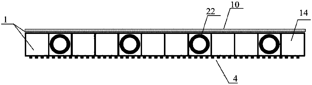
[0060] 1. The specification of the heat collecting unit is set to 600*1200mm, so the thickness of the hollow heat collecting plate with channel is set to 5mm, the channel cross-sectional area of ​​the internal grid is 5*5mm, and the material of the heat collecting plate is transparent PC carbonate hollow plate .

[0061] 2. The outer diameter of the plastic pipe used as the branch pipe is set to 4mm, and the wall thickness is 1mm. The outer diameter of the distribution / collection pipe used as the first main pipe and the second main pipe is set to 20mm, and the wall thickness is 2mm. The plastic pipe material It is PE-RT with various additives, and the color is set to carbon black.

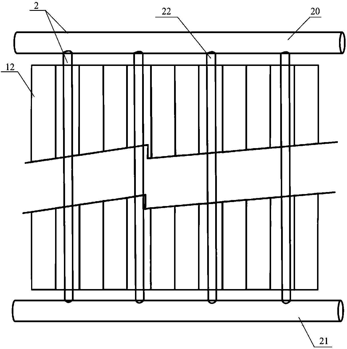
[0062] 2. Making heat collecting plate

[0063] The distance between the plastic pipes used as branch pipes is set to 20mm, occupying a channel of a hollow heat collecting plate every 20mm, and then welding the two ends to the first dry pipe and the second dry pip...

Embodiment 2

[0067] 1. Material preparation

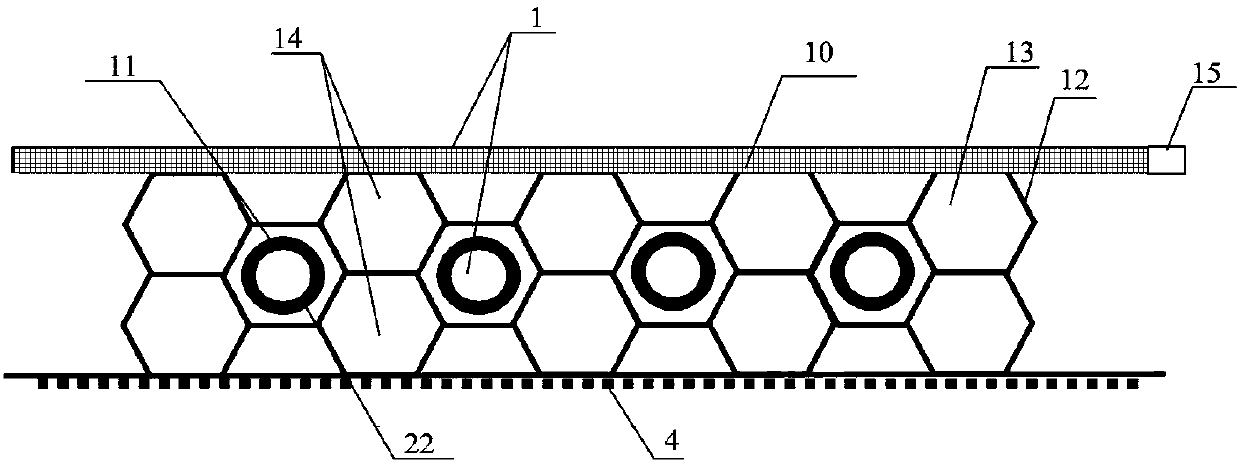
[0068] 1. The specification of the heat collecting unit is set to 1000*2000mm, so the thickness of the hollow heat collecting plate with channels is set to 18mm, and the middle channel is in the shape of three layers of honeycomb, so that each grid channel can accommodate 6mm plastic pipes to penetrate and collect heat. The board material is transparent PC carbonate hollow board.

[0069] 2. The outer diameter of the plastic pipe used as the branch pipe is set to 6mm, and the wall thickness is 1.2mm. The tube material is PE-RT with various additives, and the color is set to carbon black.

[0070] 2. Making heat collecting plate

[0071] The distance between the plastic pipes used as branch pipes is set to 20mm, and every 20mm occupies a channel in the middle layer of a hollow heat collector plate, and then welds its two ends to the first dry pipe and the second dry pipe respectively to form a collector In the heat unit, the two ends of the f...

Embodiment 3

[0075] 1. Material preparation

[0076] Such as Figure 5 As shown, the heat collecting plate in the heat collecting unit is replaced by heat collecting fins 6 with multiple longitudinally distributed arc grooves 60 inside, the specification of which is set to 600*1200mm, and the cross-sectional area of ​​the arc groove is set It is 5*5mm, and the heat collecting fin material is transparent PC carbonate polyester.

[0077] 2. The outer diameter of the plastic pipe used as the branch pipe is set to 4mm, and the wall thickness is 1mm. The outer diameter of the distribution / collection pipe used as the first main pipe and the second main pipe is set to 20mm, and the wall thickness is 2mm. The plastic pipe material It is PE-RT with various additives, and the color is set to carbon black.

[0078] 2. Making heat collecting plate

[0079] The distance between the plastic pipes used as the branch pipes 22 is set to 20mm, occupying a channel of a hollow heat collecting plate every 2...


PUM


Abstract

The invention discloses a solar photo voltage / thermal collector energy collection system which comprises at least one energy collection device. Each energy collection device comprises a photovoltaic unit used for photovoltaic conversion and a photo-thermal unit used for photo-thermal conversion. Each photo-thermal unit comprises at least one layer of grating-shaped thermal collection plate. Each grating in each thermal collection plate is through in the longitudinal direction, so that a plurality of arc-shaped containing cavities corresponding to all the gratings are defined. Each photovoltaic unit is arranged on the surface of one side of the corresponding photo-thermal unit. The containing cavities of the thermal collection plates pass through a water circulating mechanism to be connected with a water storage mechanism. The photovoltaic units are connected with an electric power storage mechanism to form the energy collection system. The solar photo voltage / thermal collector energy collection system can be suitable for large-scale mounting and application, and has the effects of being light and easy to maintain, meanwhile consciously lowering water supply temperature, adopting low-temperature heating as a main target, and being high in technical adaptability, controllable in cost and good in practical effect.

Description

technical field [0001] The invention relates to an energy collection system used in the case of renewable energy utilization. More specifically, the present invention relates to a photovoltaic-photothermal-integrated energy collection system used in the case of solar energy used to supply building energy or agricultural production of clean energy. Background technique [0002] At present, the utilization of solar energy is generally divided into two ways: one is solar photovoltaic technology, which converts the radiant energy of solar energy into electrical energy, and then converts it into alternating current used in conventional power systems, and is used to supplement various electrical equipment. It is divided into polycrystalline silicon, monocrystalline silicon and amorphous silicon, as well as photovoltaic panels and thin-film batteries; the second is solar thermal technology, which converts solar radiation energy into heat energy and continues to use it to replace ot...

Claims


Application Information

Patent Timeline
Patent Type & Authority Patents(China)
IPC IPC(8): F24S90/00H02S40/44
CPCF24S90/00H02S40/44Y02E10/40Y02E10/50Y02E10/60
Inventor 郭海新
Owner 京彩未来智能科技股份有限公司
Why Eureka
Try Eureka