Experiment method for testing abrasion difference among left tool face, right tool face and rear tool face of tool
An experimental method and flank technology, applied in the direction of manufacturing tools, measuring/indicating equipment, metal processing machinery parts, etc., can solve the problems of tool overuse, tool waste, etc., and achieve the goal of saving process costs and reducing the workload of experimental testing Effect
- Summary
- Abstract
- Description
- Claims
- Application Information
AI Technical Summary
Problems solved by technology
Method used
Image

Examples
Embodiment 1
[0036] Implementation example 1: Construction of force model of left and right cutting edges and experimental tool design
[0037] (1) In the process of machining large-pitch threads by using the axial layered cutting method, the chip movement directions on the rake face of the left and right cutting edges are different, the feeding direction of the left cutting edge is opposite to the direction of the normal vector of the machined surface, and the feeding direction of the right cutting edge The direction is the same as the normal vector direction of the machined surface, resulting in significantly different forces, such as figure 1 , figure 2 shown;
[0038] In the picture: v c is the cutting speed, v f is the axial feed speed of the tool, θ is the helix angle of the thread, a c is the cutting thickness, v 1 is the total moving speed of the left cutting edge relative to the thread surface, F x1 is the resultant force on the left cutting edge in the horizontal direction...
Embodiment 2
[0050] Implementation example 2: Experimental method of tool flank wear
[0051] (1) In order to reveal the difference in the wear of the left and right flanks of the tool under different working conditions, the two turning tools in Table 1 were used in the experiment to cut the 35CrMo specimen under dry cutting and lubrication conditions, and the specimens in the two turning experiments were all It is a right-hand thread with a pitch of 16mm, the number of starts is 1, the tooth angle is 26°, the helix angle is 2°36', the thread processing length is 160mm, the outer diameter is 120mm, and the inner diameter is 104mm;
[0052] (2) The experiment adopts the method of cutting layer by layer along one side of the tool along the axial direction, and keeps the radial cutting depth of the tool consistent with the groove depth of the trapezoidal external thread. The feed rate of the left and right layered turning in the two experiments is 0.05mm, and the speed is 10rpm; among them, t...
Embodiment 3
[0059] Implementation example 3: Differences in the wear width of the left and right flanks of the tool
[0060] (1) Cutting experiments were carried out using the experimental scheme of tool 1 in Table 2. The cutting times and cutting strokes of the left and right cutting edges are shown in Table 3 for each tool wear measurement;
[0061] Table 3 Cutting stroke of left and right cutting edges of tool 1
[0062]
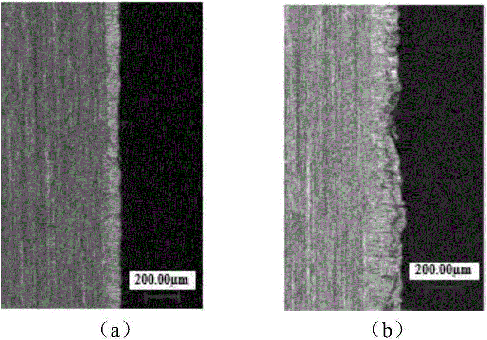
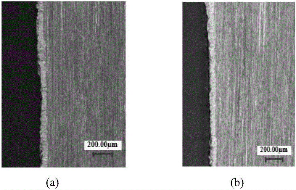
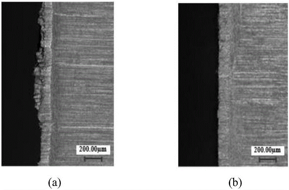
[0063] (2) Obtain the change characteristics of the flank wear width with the cutting stroke at different distances from the tool nose, such as Figure 4 , Figure 5 shown;
[0064] (3) by image 3 It can be seen that as the cutting stroke increases, there is a significant difference in the wear width of the left and right flanks of tool 1; at the same time, it is found that in the initial wear stage, the wear width of the left and right flanks is similar to the change in the cutting stroke, but there is a difference along the direction of the cutting edge; In...
PUM
 Abstract
Description
Claims
Application Information
 - R&D Engineer
- R&D Manager
- IP Professional
- Industry Leading Data Capabilities
- Powerful AI technology
- Patent DNA Extraction
Browse by: Latest US Patents, China's latest patents, Technical Efficacy Thesaurus, Application Domain, Technology Topic.
© 2024 PatSnap. All rights reserved.Legal|Privacy policy|Modern Slavery Act Transparency Statement|Sitemap