High-frequency vibration worktable for forming holes on sponge by gang drill

A high-frequency vibration, worktable technology, applied in metal processing and other directions, can solve the problems of low processing efficiency of elastomer layer, low degree of automation, low product accuracy, etc. Smooth surface without damage

Inactive Publication Date: 2016-07-20
SUZHOU INOAC ZHONGDING OFFICE MACHINE PRODS
View PDF7 Cites 3 Cited by
  • Summary
  • Abstract
  • Description
  • Claims
  • Application Information

AI Technical Summary

Problems solved by technology

[0005] The invention provides a high-frequency vibration sponge group drilling and drilling workbench, which is used to solve the problems of low processing efficiency, low degree of automation and low product precision of the elastic body layer of the current transfer roller.

Method used


Image

  • High-frequency vibration worktable for forming holes on sponge by gang drill
  • High-frequency vibration worktable for forming holes on sponge by gang drill
  • High-frequency vibration worktable for forming holes on sponge by gang drill

Examples


Embodiment Construction

[0031] The high-frequency vibration sponge group drilling and drilling workbench proposed by the present invention will be further described in detail below in conjunction with the accompanying drawings and specific embodiments. Advantages and features of the present invention will be apparent from the following description and claims. It should be noted that the drawings are all in a very simplified form and use imprecise ratios, which are only used to facilitate and clearly assist the purpose of illustrating the embodiments of the present invention.

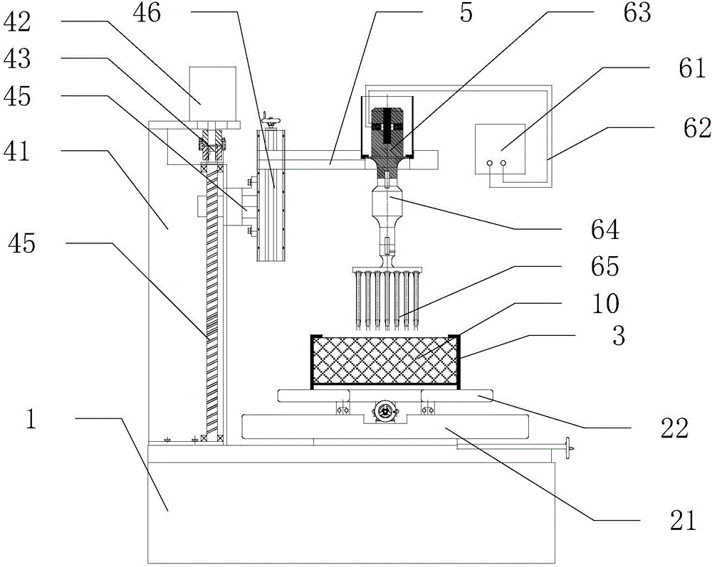
[0032] The high-frequency vibration sponge group drilling workbench of the present invention, such as figure 1 As shown, it includes a base 1, a horizontal moving mechanism set on the base 1, a fixed frame 3 set on the horizontal moving mechanism, a vertical moving mechanism set on the base 1, and a vertical moving mechanism set on the vertical moving mechanism. The support frame 5 on the mechanism and the high-frequency vibra...


PUM


Abstract

The invention relates to a high-frequency vibration worktable for forming holes on sponge by gang drill. The high-frequency vibration worktable comprises a base, a horizontal moving mechanism, a fixed frame, a vertical moving mechanism, a supporting frame and a high-frequency vibration device for forming holes on the sponge by gang drill, wherein the horizontal moving mechanism is arranged on the base; the fixed frame is arranged on the horizontal moving mechanism; the vertical moving mechanism is arranged on the base; the supporting frame is arranged on the vertical moving mechanism; the high-frequency vibration device for forming the holes on the sponge by gang drill is arranged on the supporting frame, is positioned above the fixed frame and comprises an ultrasonic generator, an ultrasonic transducer, at least one stage of amplitude-change pole and a multi-tube cutter; the ultrasonic transducer is connected with the ultrasonic generator through a wire; the at least one stage of amplitude-change pole is connected with the ultrasonic transducer; and the multi-tube cutter is connected with the amplitude-change pole. According to the high-frequency vibration worktable disclosed by the invention, holes are easily formed in the sponge by adopting a high-frequency vibration mode; workpieces can be moved in a two-dimensional plane at any trace through the horizontal moving mechanism; accurate up-down motion can be realized by a gang drill drilling device; and one-time multi-hole automatic forming of the workpieces to be processed can be realized through the fixed frame according to requirements.

Description

technical field [0001] The invention belongs to transfer printing roller processing equipment, in particular to a high-frequency vibration sponge group drilling and drilling workbench. Background technique [0002] The transfer roller of a printer or copier generally includes a metal mandrel and an elastomer layer sleeved outside the metal mandrel. The elastomer layer is usually the above-mentioned elastic material. In order to set the inner mandrel, holes need to be opened on the elastic material. . The transfer roller is the core component of a printer or copier, and has very high requirements for dimensional accuracy and flatness of shape. But elastic materials are prone to deformation under slight pressure or torsion and tend to resist downward cutting or drilling actions by compressing or deforming. [0003] At present, the following two methods can be considered for drilling holes on the sponge: one adopts the tool drilling process, such as the above-mentioned techni...

Claims


Application Information

Patent Timeline
Patent Type & Authority Applications(China)
IPC IPC(8): B26F1/16B26D7/08B26D7/26B26D7/01B26D5/02
CPCB26F1/16B26D5/02B26D7/01B26D7/086B26D7/2614
Inventor 吴安殷振李超群吴维龙李小华杨鑫铭靳家乐
Owner SUZHOU INOAC ZHONGDING OFFICE MACHINE PRODS
Why Eureka
Try Eureka