A high-frequency longitudinal-torsion composite vibrating sponge array strip-taking workbench and its application

A composite vibration and worktable technology, applied in metal processing and other directions, can solve the problems of low product accuracy, low automation, and low processing efficiency of the elastomer layer, and achieve high aperture dimensional accuracy, stable strip removal process, and automated processing significance. significant effect

Inactive Publication Date: 2017-08-15
SUZHOU UNIV OF SCI & TECH
View PDF1 Cites 0 Cited by
  • Summary
  • Abstract
  • Description
  • Claims
  • Application Information

AI Technical Summary

Problems solved by technology

[0005] The invention provides a high-frequency longitudinal-torsion compound vibrating sponge array strip-taking workbench, which is used to solve the problems of low processing efficiency, low degree of automation and low product precision of the elastic body layer of the current transfer roller.

Method used


Image

  • A high-frequency longitudinal-torsion composite vibrating sponge array strip-taking workbench and its application
  • A high-frequency longitudinal-torsion composite vibrating sponge array strip-taking workbench and its application
  • A high-frequency longitudinal-torsion composite vibrating sponge array strip-taking workbench and its application

Examples


Embodiment 1

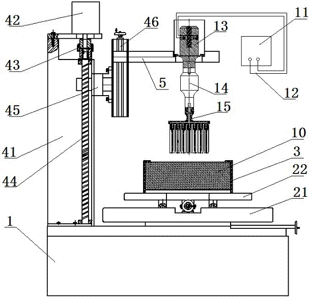
[0054] Such as figure 1 As shown, the horizontal movement mechanism includes a longitudinal movement platform 21 and a transverse movement platform 22. The longitudinal movement platform 21 driven by a ball screw is connected to the base 1 by bolts, and the transverse movement platform 22 driven by a ball screw is connected by a bolt. The connection is arranged on the longitudinal movement platform 21, and the fixed frame 3 is arranged on the transverse movement platform 22 through the bolt connection. Through the cooperative drive of the longitudinal movement platform 21 and the transverse movement platform 22, the fixed frame 3 drives the workpiece 10 to be processed to realize horizontal and vertical movement. Arbitrary trajectory movement in a composite 2D plane.

[0055] continue to see figure 1 , the high-frequency longitudinal-torsion compound vibration sponge array strip-taking device includes an ultrasonic generator 11, an ultrasonic transducer 13 connected to the ul...

Embodiment 2

[0075] The difference from Embodiment 1 is that the tube body mounting plate 152 also includes a cover 1523 for the internally threaded hole 1522 . It is used for the closure of the internally threaded hole 1522 that is not connected to the pipe body.

[0076] For example, when the diameter of the elastomer layer of the pre-processed transfer roller is large, such as Figure 8 As shown, the external thread head 1533 of the pipe body matches the internal thread hole 1522, and the cavity 153 matches the size of the pre-processed hole.

[0077] Since the outer diameter of the tube becomes larger, it is impossible to sequentially arrange the tubes on the tube mounting plate 152 , and the unused internal threaded hole 1522 is closed by the cover 1523 .

[0078] Using the processing process described in Embodiment 1, the processing of multiple cylindrical hollow strip blanks-the elastomer layer 23 of the transfer roller can be realized.


PUM


Abstract

The invention relates to a high-frequency longitudinal torsion composite vibration sponge array strip fetching workbench and an application thereof. The workbench comprises a base, a horizontal movement mechanism, a fixing frame, a vertical movement mechanism, a supporting frame and a high-frequency longitudinal torsion composite vibration sponge array strip fetching device. The high-frequency longitudinal torsion composite vibration sponge array strip fetching device comprises an ultrasonic generator, an ultrasonic transducer, at least one stage of amplitude-change pole and a multi-tube tool. The multi-tube tool comprises a connector connected with the amplitude-change poles, a tube body placement plate, a plurality of tube bodies and a cutting edge, wherein one end of each tube body is detachably connected with the tube body placement plate; the other end of each tube body stretches out of the cutting edge; and each tube body is provided with a longitudinal torsion composite vibration conversion structure. Strips are fetched from sponges easily in a high-frequency vibration mode; workpieces move on any trace in a two-dimension plane through the horizontal movement mechanism; the array strip fetching device can move up and down accurately; and by means of the fixing frame, multiple workpieces to be machined are molded automatically at a time.

Description

technical field [0001] The invention belongs to transfer printing roller processing equipment, in particular to a high-frequency longitudinal-torsion composite vibrating sponge array strip-taking workbench. Background technique [0002] The transfer roller of a printer or copier generally includes a metal mandrel and an elastomer layer sleeved outside the metal mandrel. The elastomer layer is usually the above-mentioned elastic material. In order to set the inner mandrel, holes need to be opened on the elastic material. . The transfer roller is the core component of a printer or copier, and has very high requirements for dimensional accuracy and flatness of shape. But elastic materials are prone to deformation under slight pressure or torsion and tend to resist downward cutting or drilling actions by compressing or deforming. [0003] At present, the following two methods can be considered for taking strips on the sponge: one adopts tool drilling, such as the above-mention...

Claims


Application Information

Patent Timeline
Patent Type & Authority Patents(China)
IPC IPC(8): B26D1/06B26D7/08B26D7/18B26D7/01
CPCB26D1/0006B26D1/06B26D7/01B26D7/086B26D7/1854B26D2001/006B26D2007/013
Inventor 华泽李艳殷振马乐文范道全吴家玮楼鸣胡清柱张首贺邹同兵
Owner SUZHOU UNIV OF SCI & TECH
Why Eureka
Try Eureka