Glass tank furnace with high melting rate

A glass tank kiln and melting rate technology, applied in glass production, glass furnace equipment, glass manufacturing equipment, etc., can solve the problems of low operation efficiency and operation yield, too large furnace area, high bottom temperature, and prolong life. , the effect of reducing the furnace area, reducing energy consumption and carbon dioxide emissions

Active Publication Date: 2016-07-20
JUSHI GRP CO
View PDF3 Cites 23 Cited by
  • Summary
  • Abstract
  • Description
  • Claims
  • Application Information

AI Technical Summary

Problems solved by technology

[0002] At present, with the shortage of energy, the cost of thermal equipment with high energy consumption such as glass tank kilns is also getting higher and higher; at this stage, the aspect ratio of domestic unit kilns is generally controlled between 3-3.3, and its melting rate (melting rate It refers to the amount of glass melted by the melting area of ​​the unit kiln per square meter per day. The glass flow rate is the actual output of the kiln. An index of the level) is generally below 2.4 tons / day*square meter. Due to the backwardness of its equipment and combustion technology, and the kiln area is too large and the bottom temperature is high, there are low melting rate, high investment, high energy consumption, and poor operation. Disadvantages such as low efficiency and job yield
[0003] Therefore, in view of the above existing problems, it is urgent to design and provide a glass tank furnace with a high melting rate to solve the shortcomings of the existing tank furnaces such as low melting rate and high energy consumption.

Method used


Image

  • Glass tank furnace with high melting rate
  • Glass tank furnace with high melting rate
  • Glass tank furnace with high melting rate

Examples


specific Embodiment 1

[0038] In this specific embodiment, a horizontal pure oxygen burner is provided.

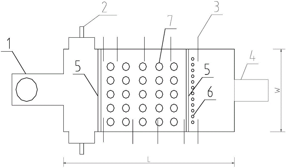
[0039] see figure 1 , figure 2 , the high melting rate kiln includes flue 1, feeder 2, melting part and main passage, wherein the flue is arranged on the back wall of the kiln, L in the figure indicates the length of the kiln, W indicates the width of the tank, high melting The length-to-width ratio of the kiln is 2.32, the melting rate is 2.97 tons / day*square meter, and the feeding port and ear pool are arranged on both sides of the kiln. This specific embodiment includes a horizontal pure oxygen burner 3, a liquid flow hole 4, a bottom kiln ridge 5, a bubble 6 and an electrode 7, wherein there are 5 pairs of pure oxygen burners 3 arranged horizontally on both sides of the parapet Above, five rows of electrodes 7 are arranged at the bottom of the pool kiln, and each row is provided with five electrodes; kiln ridges 5 are arranged before and after the electrodes 7, and bubbles 6 are arranged ...

specific Embodiment 2

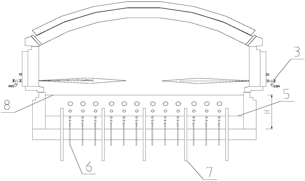
[0040] An inclined pure oxygen burner is provided in this specific embodiment.

[0041] Such as image 3 As shown, the length-to-width ratio of the high melting rate tank kiln in this embodiment is 2.36, and the melting rate is 2.76 tons / day*square meter. Pure oxygen burners are installed obliquely on the parapets on both sides.

specific Embodiment 3

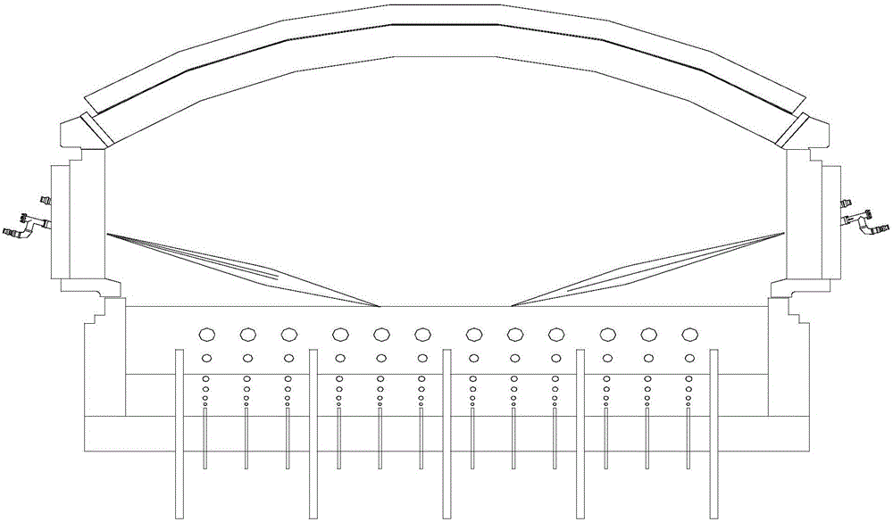
[0042] In this specific embodiment, the pure oxygen burner located on the top of the mountain is called the top pure oxygen burner 11 .

[0043] Such as Figure 4 As shown, the difference between the structure of the high melting rate tank kiln in this specific embodiment and the high melting rate tank kiln in specific embodiment 1 is that it does not include the pure oxygen burner arranged on the parapet, only includes the Oxygen burners on the roof. Specifically, there are three pure oxygen burners 11 on the top of the kiln, and they are arranged on the large wall of the kiln. There are four rows of electrodes 7 at the bottom of the kiln, four of which are arranged in the first row, and each row is arranged in the second to fourth rows. 6 pieces; kiln sills 5 are arranged on the front and back of the electrode 7, and the bubbles 6 are arranged on the kiln sill.


PUM

PropertyMeasurementUnit
depthaaaaaaaaaa

Abstract

The invention discloses a glass tank furnace with high melting rate. The ratio of the length of the glass tank furnace to the width of the glass tank furnace is 2.3-2.8. The glass tank furnace has the advantages that the area of the tank furnace is reduced and the length-width ratio of the tank furnace is optimized so as to reduce heat loss; reasonable liquid glass tank depth is designed to improve the bottom temperature of the tank furnace and guarantee the quality of liquid glass; a pure-oxygen burner and an auxiliary capacitor provides sufficient energy to increase the melting ability and heating efficiency of the tank furnace, and the energy consumption and the discharge amount of carbon dioxide are lowered greatly; furnace ridges at the bottom of the tank furnace increase the outlet temperature of the liquid glass, lower energy consumption, lower the furnace bottom temperature of an electrode area, prolong the service life of the furnace bottom and guarantee the increasing of auxiliary electric energy proportion; bubbling at the bottom of the tank furnace increases the return strength of the liquid glass and increases the melting ability and the quality of the liquid glass; to sum up, the melting rate of the tank furnace can be increased effectively, and the energy consumption can be lowered.

Description

technical field [0001] The invention relates to glass pool kiln technology, in particular to a glass pool kiln with high melting rate. Background technique [0002] At present, with the shortage of energy, the cost of thermal equipment with high energy consumption such as glass tank kilns is also getting higher and higher; at this stage, the aspect ratio of domestic unit kilns is generally controlled between 3-3.3, and its melting rate (melting rate It refers to the amount of glass melted by the melting area of ​​the unit kiln per square meter per day. The glass flow rate is the actual output of the kiln. An index of the level) is generally below 2.4 tons / day*square meter. Due to the backwardness of its equipment and combustion technology, and the kiln area is too large and the bottom temperature is high, there are low melting rate, high investment, high energy consumption, and poor operation. Shortcomings such as low efficiency and job yield. [0003] Therefore, in view o...

Claims


Application Information

Patent Timeline
Patent Type & Authority Applications(China)
IPC IPC(8): C03B5/03
CPCC03B5/03C03B2211/24C03B5/16C03B5/193C03B5/2353Y02P40/50
Inventor 方长应俞力锋沈培军赵仙良严育仓翁晓东
Owner JUSHI GRP CO
Why Eureka
Try Eureka