Multi-head trenching machine

A trough forming machine, multi-head technology, applied in the direction of earth mover/shovel, construction, etc., can solve the problems of low trough forming efficiency, complex structure, expensive equipment, etc., and achieve the effect of fast grooving speed.

Inactive Publication Date: 2016-07-20
哈尔滨通用液压机械制造有限公司
View PDF0 Cites 0 Cited by
  • Summary
  • Abstract
  • Description
  • Claims
  • Application Information

AI Technical Summary

Problems solved by technology

[0002] At present, most of the groove-forming equipment for building underground diaphragm walls have the characteristics of low groove-forming efficiency, expensive equipment, and complicated structures.

Method used


Image

  • Multi-head trenching machine
  • Multi-head trenching machine

Examples


Embodiment Construction

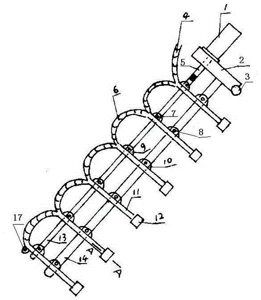
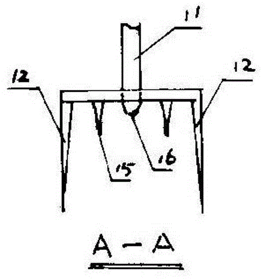
[0013] The accompanying drawing is a specific embodiment of the present invention, which includes a panel 2 on the upper part of the slotting machine, a support 3 at the lower end of the panel, a hydraulic cylinder 1 on the right side of the panel is fixed on the panel, and the output shaft 5 of the cylinder passes through the panel It is hinged with the upper end of the pull rod 13, the upper end of the main rod 14 is fixed with the panel, the knife bar 11 is provided with several according to the size of the groove depth, the upper part of each knife bar is provided with a hinge seat A9, the middle part is provided with a hinge seat B10, and the lower end is provided with a hinge seat A9. There is a water nozzle 16, the two sides of the water nozzle are respectively provided with a knife tooth 15, and the outermost sides of the two knife teeth are respectively provided with a side knife 12, the side knife is a rectangle with a certain width and a certain height, and the bottom...


PUM


Abstract

A multi-head trenching machine comprises a panel at the upper portion of the trenching machine, and a support at the lower end of the panel. A hydraulic oil cylinder on the right side of the panel is fixed to the panel, and an oil cylinder output shaft of the hydraulic oil cylinder penetrates the panel and is hinged to the upper end of a pull rod. The upper end of a main rod and the panel are fixed. A plurality of cutter rods are arranged according to the trenching depth. A hinge base A is arranged at the upper portion of each cutter rod, a hinge base B is arranged in the middle portion of each cutter rod, a water nozzle is arranged at the lower end of each cutter rod, and a cutter tooth is arranged on each of the two sides of each water nozzle, wherein an edge cutter is arranged on the outermost side of each of the two cutter teeth. Two branches are arranged at the uppermost end of each cutter rod, and the branches at the upper ends of every two adjacent cutter rods are connected through a connecting hose. The hinge base A at the upper portion of each cutter rod and the pull rod are hinged through a hinge shaft A. The hinge base B in the middle portion of each cutter rod and the main rod are hinged through a hinge shaft B. The multi-head trenching machine is a special machine tool for building underground diaphragm walls.

Description

technical field [0001] The invention relates to a groove forming machine, in particular to a multi-head groove forming machine for underground continuous wall groove formation. Background technique [0002] At present, most of the groove-forming equipment for building underground diaphragm walls have the characteristics of low groove-forming efficiency, expensive equipment, and complicated structures. Contents of the invention [0003] The present invention makes up for the shortcomings of the above groove forming equipment, and provides a multi-head groove forming machine with high efficiency, low cost and simple structure. [0004] The present invention is achieved through the following technical solutions: [0005] A multi-head grooving machine, including a panel on the upper part of the grooving machine, a support at the lower end of the panel, a hydraulic cylinder on the right side of the panel is fixed on the panel, the output shaft of the cylinder passes th...

Claims


Application Information

Patent Timeline
IPC IPC(8): E02F5/02E02F5/14
Inventor 孙树德
Owner 哈尔滨通用液压机械制造有限公司
Why Eureka
Try Eureka