
Mounting rack for spring-loaded thrust meter

The technology of a spring dynamometer and a mounting frame is applied in the measurement device, the measurement of fluid pressure, the measurement of elastic deformation force through the measurement gauge, etc., and can solve the problems of inconvenient installation and the like

Inactive Publication Date: 2016-07-20
博艳萍
View PDF7 Cites 0 Cited by
  • Summary
  • Abstract
  • Description
  • Claims
  • Application Information

AI Technical Summary

Problems solved by technology

Existing dynamometers are inconvenient to install

Method used


Image

  • Mounting rack for spring-loaded thrust meter
  • Mounting rack for spring-loaded thrust meter

Examples


Embodiment Construction

[0012] The preferred embodiments of the present invention will be described in detail below in conjunction with the accompanying drawings, so that the advantages and features of the present invention can be more easily understood by those skilled in the art, so as to define the protection scope of the present invention more clearly.

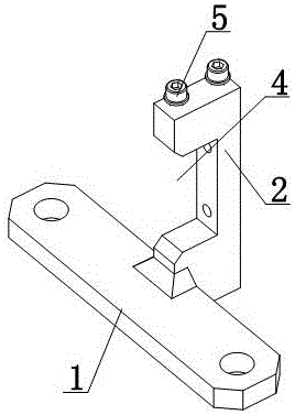
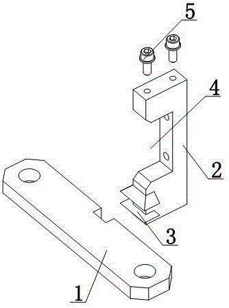
[0013] Such as figure 1 and figure 2 As shown, a spring dynamometer installation frame includes a base plate 1, a bracket 2 is provided on the base plate 1, a slot 3 is provided at the bottom of the bracket 2, and the slot 3 clamps the base plate 1; the bracket 2 is provided with a mounting groove 4, The top of the bracket 2 is provided with a fixed pin 5, the upper end of the fixed pin 5 is buckled on the top of the bracket 2, and the lower end of the fixed pin 5 is set at the position of the installation groove 4; both ends of the bottom plate 1 are provided with fixing holes, and the bottom plate 1 is a block structure .

[0014] The spring...


PUM


Abstract

The invention discloses a mounting rack for a spring-loaded thrust meter. The mounting rack comprises a base plate; a support is arranged on the base plate; a clamp groove is formed in the bottom of the support and is used for clamping the base plate; and a mounting groove is formed in the support. Fixed pins are arranged at the top of the supports; the upper ends of the fixed pins are buckled to the top of the support; and the lower ends of the fixed pins are arranged at the mounting groove. According to the invention, the spring-loaded thrust meter can be installed at the mounting groove of the support and effects of fixation and support can be realized by using the base plate, so that installation of the spring-loaded thrust meter becomes convenient; and the spring-loaded thrust meter can carry out spring force testing on the spring conveniently.

Description

technical field [0001] The invention relates to a mounting frame, in particular to a spring force gauge mounting frame. Background technique [0002] Dynamometers come in a variety of constructions, but their main component is a curved, resilient steel leaf or helical spring. When the external force deforms the elastic steel sheet or spring, the pointer is driven to rotate through a transmission mechanism such as a lever, and the position where the pointer stops on the dial is the value of the external force. Existing dynamometers are inconvenient to install. Contents of the invention [0003] The present invention mainly solves the technical problems existing in the prior art, thereby providing a spring dynamometer that can be installed in the installation groove of the bracket, and can be fixed and supported by the bottom plate, thereby facilitating the spring dynamometer The installation of the meter is convenient for the spring dynamometer to test the spring force of...

Claims


Application Information

Patent Timeline
Patent Type & Authority Applications(China)
IPC IPC(8): G01L1/04G01L7/02
CPCG01L1/04G01L7/022
Inventor 博艳萍
Owner 博艳萍
Learn More