Internal potential response-based inertia control method and device for full-power wind generator

A wind turbine and inertia control technology, applied in wind power generation, single grid parallel feeding arrangement, etc., can solve the problems of rapid frequency and drastic changes, etc., and achieve the goal of improving inertia response speed, increasing inertia, and suppressing system frequency fluctuations Effect

Active Publication Date: 2016-07-20
HUAZHONG UNIV OF SCI & TECH +2
View PDF1 Cites 16 Cited by
  • Summary
  • Abstract
  • Description
  • Claims
  • Application Information

AI Technical Summary

Benefits of technology

This technology helps prevent damage caused by rapid variations or disturbances affects an AC electric machine's ability to react properly with changing electrical conditions. It involves controlling the output current from one part (the generator) based upon another part called the battery charger. When there are no problems with the load being driven through it, the motor operates more efficiently because less fuel needs to run during peak hours compared to when other parts have trouble doing their job well together. Additionally, if some problem arises while driving upgrades for new generators, the process automatically compensated increases efficiency without stopping production until they get back into operation again. Overall, these improvements improve the performance and durability of AC machines over longer periods of time than before any maintenance work was done.

Problems solved by technology

This patented technical problem addressed in this patents relates to improving the performance and reliability of fully-functional wind electricity generating systems due to their ability to operate at different frequencies depending upon varying loads caused by changes over time. Current methods have limitations such as slow response times and limited input/output capabilities.

Method used


Image

  • Internal potential response-based inertia control method and device for full-power wind generator
  • Internal potential response-based inertia control method and device for full-power wind generator
  • Internal potential response-based inertia control method and device for full-power wind generator

Examples


Embodiment Construction

[0039] In order to make the object, technical solution and advantages of the present invention clearer, the present invention will be further described in detail below in conjunction with the accompanying drawings and embodiments. It should be understood that the specific embodiments described here are only used to explain the present invention, not to limit the present invention.

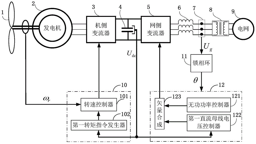
[0040] The present invention relates to a new type of inertia control method applied to grid-connected full-power wind power generators and other grid-connected converter devices including voltage source type or current source type. More specifically, it relates to a method through optimization The internal potential response of the grid-connected converter device is used to realize the control mode in which the power supply shows inertia to the grid. The present invention mainly takes the application of the inertia control method based on optimized internal potential response in a full-power wind ...


PUM


Abstract

The invention discloses an internal potential response-based inertia control method and device for a full-power wind generator. When a full-power wind power generator system suddenly increases or reduces a load, a phase-locked loop cannot accurately lock the phase and the frequency of a power grid immediately by reducing the bandwidth of the phase-locked loop and changing the damping ratio of the phase-locked loop, so that a DC bus capacitor voltage correspondingly changes due to a sudden change of the power grid; a DC bus voltage is not adjusted to a reference value too fast by reducing the bandwidth of a DC bus voltage control loop and adjusting the damping ratio of a DC bus voltage loop; the inertia is shown for the power grid by a fast response of the DC bus voltage; difference operation is carried out on a DC bus measurement value and a DC bus voltage instruction value; the difference value is multiplied by a proportion coefficient to obtain an additional instruction; the additional instruction is added to a rotating speed loop to utilize rotation energy of a full-power wind generator set, so that the full-power wind generator set can provide an inertia support to the system. According to the internal potential response-based inertia control method and device for the full-power wind generator, a fast frequency and an acute change caused by a low rotational inertia of the system are avoided.

Description


Claims


Application Information

Patent Timeline
Owner HUAZHONG UNIV OF SCI & TECH
Why Eureka
Try Eureka