

Method and device for hierarchical beam access
An access method and beam technology, applied in the field of communication, can solve problems such as inability to efficiently obtain optimal beams
- Summary
- Abstract
- Description
- Claims
- Application Information
AI Technical Summary
Problems solved by technology
Method used
Image

Examples
Embodiment 1
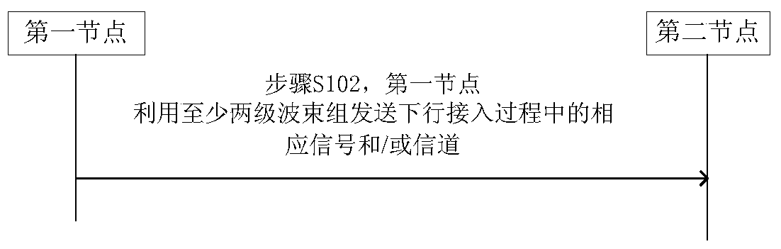
[0200] Figure 9 is a schematic diagram of a two-stage beam group access training process according to an embodiment of the present invention, as shown in Figure 9 As shown, the first node uses the first-level downlink transmission beam group to transmit a channel and / or signal with beam characteristics, and the channel and / or signal information is used for identification, synchronization, indication of access configuration information, and notification of downlink transmission beams At least one of the system configuration information, the first-level downlink sending beam group includes at least one first-level downlink beam. The indicated access configuration information includes at least one of time-frequency code resources of the first level uplink transmit beam group, uplink access signal and / or channel transmit power indication information.
[0201] The second node detects, on the predefined or configured time-frequency code resources, the channel and / or signal with b...
Embodiment 2
[0221] The first node uses N downlink sending beams to send at least one of the following signals and channels on the carrier: a synchronization signal, a downlink discovery signal, downlink system information, and uplink access configuration information. The N beams can meet the above basic channel coverage area requirements of the first node. The discovery signal is used to indicate the transmission beam used by the first node on the resource corresponding to the second node.
[0222] The N downlink beams form a first-level downlink sending beam group.
[0223] Optionally, the synchronization signal may be used to indicate the transmission beam used by the first node on the resource corresponding to the second node, and in this case, the first node does not need to additionally send a discovery signal.
[0224] Optionally, the downlink system information may be used to indicate to the second node the downlink transmission beam used by the first node on the corresponding res...
Embodiment 3
[0257] In Embodiment 1 and Embodiment 2, when the second node feeds back the index information of each beam in the second-level downlink transmission beam group, it may carry the quality indication information or correlation information corresponding to each beam in the second-level downlink transmission beam group. The priority information is used to indicate channel quality information and / or priority information corresponding to each beam in the second-level downlink beams of the first node. The first node may select the optimal one or more downlink transmission beams according to the corresponding quality information and / or priority information using a predefined or configured principle to form a first-level downlink transmission beam group.
[0258] In Embodiment 1 and Embodiment 2, when the first node indicates to the second node the index information of each beam in the second-level uplink transmission beam group, it may carry the quality of each beam in the second-level...
PUM
 Abstract
Description
Claims
Application Information