Unlock instant, AI-driven research and patent intelligence for your innovation.

Panel Light Guide

A technology of a light guide device and a panel, which is applied to lighting devices, components of lighting devices, optics, etc., can solve the problem of limited lighting range, etc., and achieve the effect of increasing the lighting range.

Active Publication Date: 2019-05-21
苏州市天启新材料科技有限公司
View PDF5 Cites 0 Cited by
  • Summary
  • Abstract
  • Description
  • Claims
  • Application Information

AI Technical Summary

Problems solved by technology

The light-emitting diode is a point light source, and its illuminated range is very limited.

Method used


Image

  • Panel Light Guide
  • Panel Light Guide
  • Panel Light Guide

Examples


Embodiment Construction

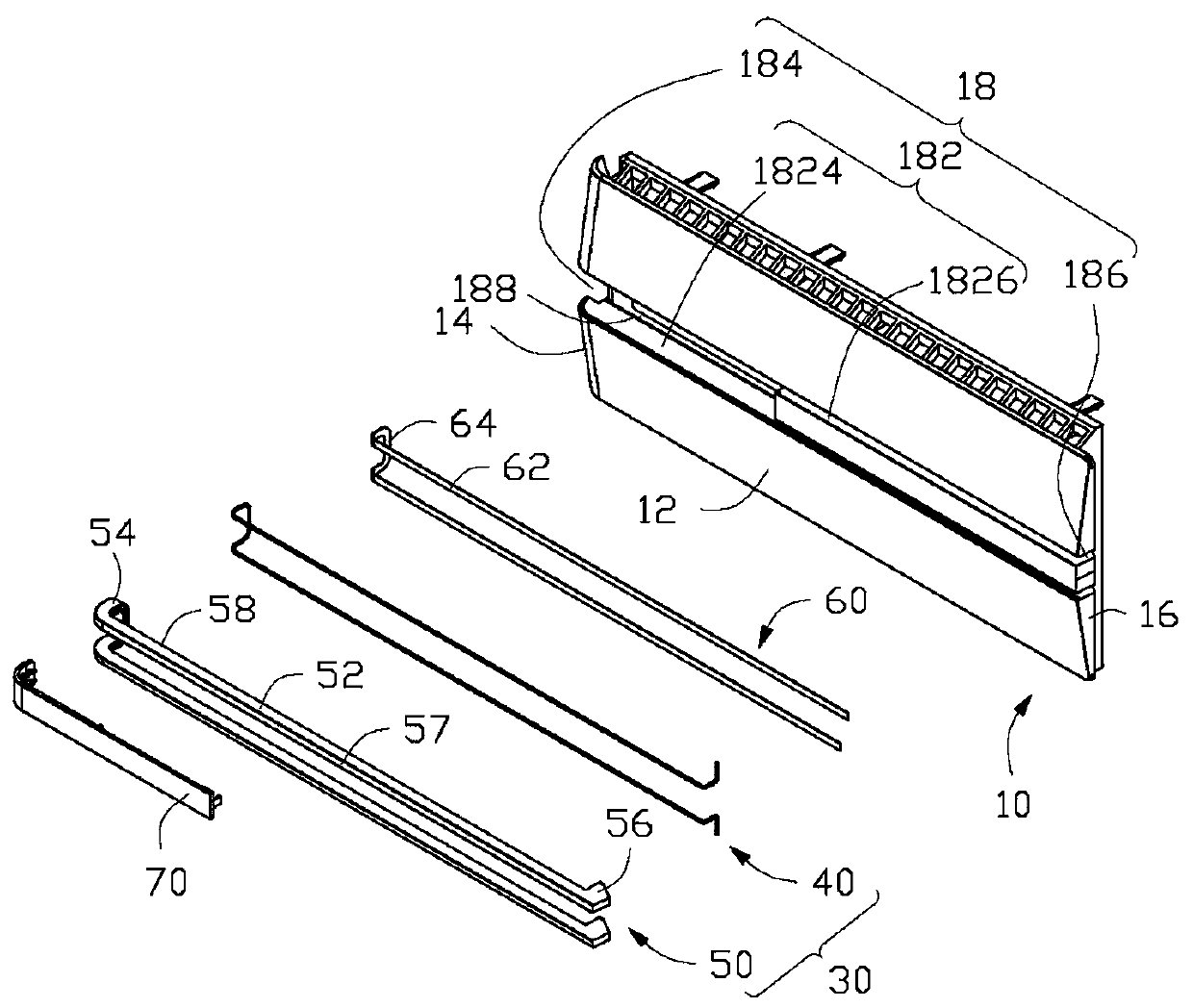
[0022] Please also see figure 1 and figure 2 , in a preferred embodiment of the present invention, a panel light guide device includes a panel 10, a light guide structure 30, a shading member 60, a cover plate 70 and two fixed to the inner wall of the panel 10 Light source 80.

[0023] The panel 10 includes a front wall 12 , a first side wall 14 and a second side wall 16 connected to the front wall 12 . The panel 10 defines a receiving portion 18 from the front wall 12 , and the receiving portion 18 includes a receiving groove 182 , a first installation groove 184 and a second installation groove 186 . The receiving groove 182 is located on the front wall 12, the receiving groove 182 extends to the first side wall 14 to form the first mounting groove 184, and the receiving groove 182 extends to the second side wall The second mounting groove 186 is formed on the 16.

[0024] The receiving groove 182 includes a first receiving groove 1824 and two second receiving grooves 1...


PUM


Abstract

An electronic device bezel includes a front panel, a light source, a light transmitting member, and a light guiding member mounted in the light transmitting member. The light source is mounted on an inner side of the front panel. The light transmitting member mounted on an outer side of the front panel. An end of the light guiding member extends through the front panel and is aligned with the light source to guide a plurality of light beams emitted from the light source to the light transmitting member.

Description

technical field [0001] The invention relates to a panel light guide device. Background technique [0002] Fashionable and personalized electronic products are more and more favored by consumers. For designers, only by designing delicate and novel products can they impress consumers and win business opportunities. In order to obtain better visual effects, light-emitting diodes are installed on the panels of the electronic products to make them bright, so that the electronic products are more attractive to customers. The light-emitting diode is a point light source, and its illuminated range is very limited. Contents of the invention [0003] In view of the above, it is necessary to provide a panel light guide device with a wider illumination range. [0004] A light guide device for a panel, comprising a panel, a light guide structure and a light source fixed on the inner wall of the panel, a housing portion is set on the panel, and the light guide structure includes a tr...

Claims


Application Information

Patent Timeline
Patent Type & Authority Patents(China)
IPC IPC(8): F21V8/00F21V17/10
CPCG02B6/001
Inventor 王良津杨年元王帅国
Owner 苏州市天启新材料科技有限公司