Lateral LED street lamp

A technology of LED street lamps and lamp holders, applied in lampshades, circuit layout, outdoor lighting, etc., can solve the problems of wasting electric energy, increasing power consumption, and increasing construction costs, and achieve the value of widespread application, reduce density requirements, and reduce transparency The effect of light loss

Inactive Publication Date: 2014-09-24
卓仲表
View PDF5 Cites 0 Cited by
  • Summary
  • Abstract
  • Description
  • Claims
  • Application Information

AI Technical Summary

Problems solved by technology

[0003] The problems of existing street lamps of this type mainly contain two points; one, the bulb is affected by the shape of the lampshade and the transparent cover, and usually can only illuminate a small area under the lamp, so in order to ensure a certain brightness for the whole street, only It can increase the layout density of street lamps, which increases the construction cost and power consumption; 2. Although the reflective surface of polished aluminum has a high initial reflective rate, after a period of use and passivation, usually only It can be maintained at about 85%, and the initial light transmittance of the transparent cover of the street lamp is only about 90%. There are a lot of street lamps and the height is also high, which cannot be cleaned regularly by sanitation workers, and the transparent cover faces the ground, and it cannot be cleaned naturally by rainwater. Therefore, after a period of use, due to the influence of dust and other factors, the light transmittance is often less than 70%, so that the actual light utilization rate of the entire street lamp to the bulb is only 65%, wasting a lot of electric energy, and the number of urban street lamps is large. Therefore, the total energy wasted is considerable

Method used


Image

  • Lateral LED street lamp
  • Lateral LED street lamp
  • Lateral LED street lamp

Examples


Embodiment 1

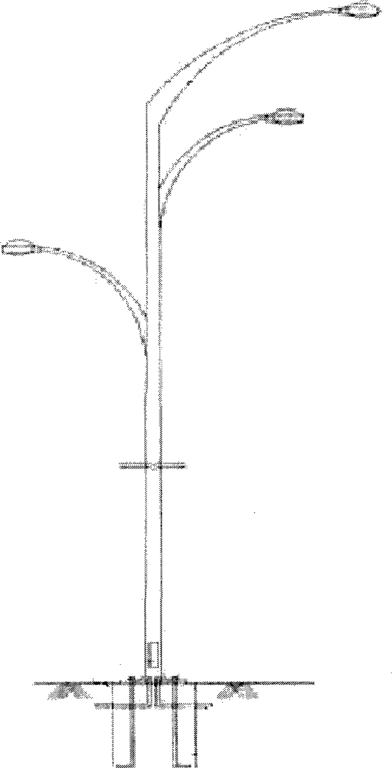
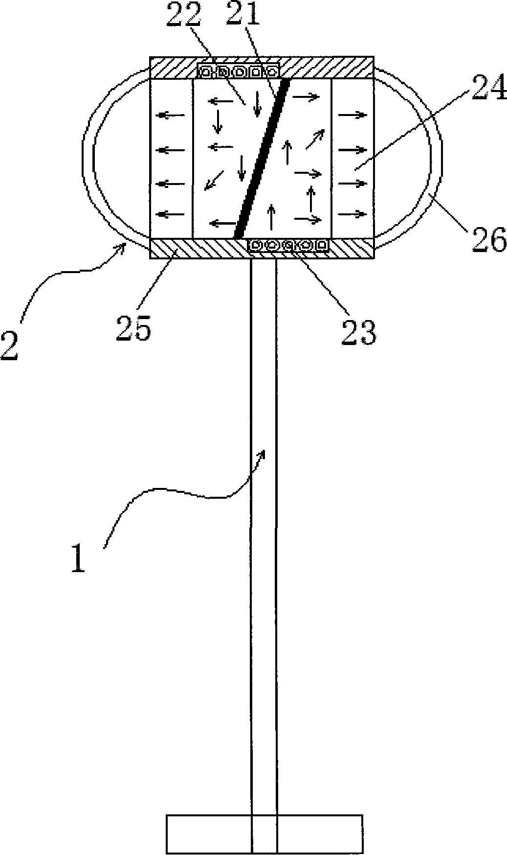
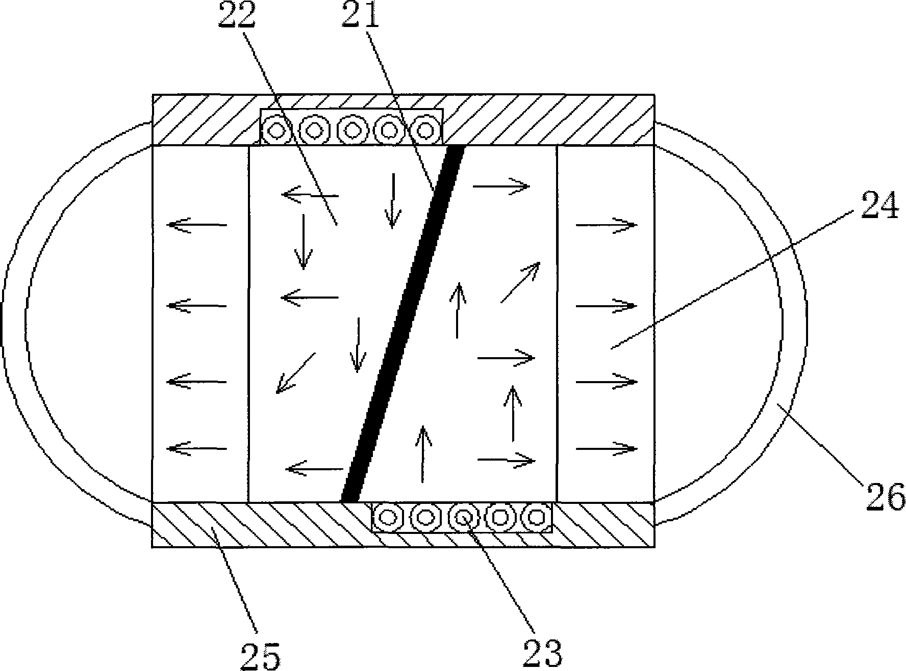
[0019] Such as figure 2 , 3 As shown, a side-facing LED street lamp is composed of two parts: a light pole 1 and a lamp head assembly 2. The light head assembly 2 is arranged on the top of the light pole 1. The light head assembly 2 includes a reflector 21 and a pair of light guide plates. 22. A pair of LED light source groups 23, a pair of diffuser plates 24, a lamp housing 25 and a pair of transparent curved lampshades 26, the lamp housing 25 is a box with openings at both ends, and a pair of transparent curved lampshades 26 It is fixedly installed at the openings at both ends of the lamp housing 25. The reflector 21 is arranged at the centerline of the lamp housing 25. A pair of light guide plates 22 are symmetrically arranged on both sides of the reflector 21. The edge of the diffuser 24 Positioning columns are provided, and the diffuser plate 24 is fixedly installed in the lamp housing 25 through the positioning columns. The diffuser plate 24 is arranged on the light-em...


PUM


Abstract

The invention relates to the field of communal facilities, in particular to a street lamp, and discloses a lateral LED street lamp. The lateral LED street lamp is composed of a lamp pole and a lamp cap assembly. The lamp cap assembly is arranged at the top of the lamp pole and comprises a reflection plate, a pair of light guide plates, a pair of LED light source sets, a pair of diffusion plates, a lamp shell and a pair of transparent curved lampshades, the lamp shell is a box with openings in the two ends, the transparent curved lampshades are fixedly arranged at the openings in the two ends of the lamp shell, the reflection plate is arranged on the central line in the lamp shell, the light guide plates are arranged on the two sides of the reflection plate in a central symmetry mode, the diffusion plates are arranged on the light emitting faces of the light guide plates, and the LED light source sets are arranged on the light entering faces of the light guide plates. The cost of the street lamp is lowered, the structure is simplified, and meanwhile losses caused by light reflection are basically avoided. Light-transmitting losses caused by dust are reduced, the light source utilization rate can be kept about 85 percent in the long-time work, and important significance in energy saving and environmental protection is achieved.

Description

technical field [0001] The invention relates to the field of public facilities, in particular to a street lamp. Background technique [0002] In a modern city, in order to ensure the needs of urban lighting, a row of street lamps will be installed on both sides of each road as lighting equipment; existing street lamps such as figure 1 As shown, it is usually composed of a light pole fixed vertically on the ground, and a lamp head is fixed on the top of the light pole; the welding method of the light pole is automatic submerged arc welding, the welding is reliable, the surface is smooth, and there are no obvious pores, welding spots, Welding defects such as undercuts, ultrasonic flaw detection inspection, steel rod anti-corrosion treatment adopts internal and external hot-dip galvanizing, the galvanizing process has gone through pickling, hot-dip galvanizing, water washing, phosphating, passivation and other processes, the surface of the galvanized layer is smooth and beautif...

Claims


Application Information

Patent Timeline
Patent Type & Authority Applications(China)
IPC IPC(8): F21S8/08F21V13/00F21V3/02F21V23/00F21W131/103F21Y101/02F21Y115/10
Inventor 卓仲表
Owner 卓仲表
Why Eureka
Try Eureka