Supercharge Your Innovation With Domain-Expert AI Agents!

Actuator with enhanced magnetic spring function for personal care appliance

A personal care and actuator technology, applied in medical science, teeth cleaning, dentistry, etc., to achieve the effect of lower manufacturing cost, lower spring stiffness requirements, and reduced magnet volume

Active Publication Date: 2016-08-24
KONINKLJIJKE PHILIPS NV
View PDF5 Cites 0 Cited by
  • Summary
  • Abstract
  • Description
  • Claims
  • Application Information

AI Technical Summary

Problems solved by technology

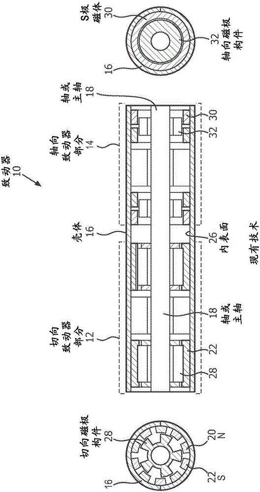
[0006] figure 1 A disadvantage of the prior art actuator 10 is that the two actuator parts are defined as separate actuators

Method used


Image

  • Actuator with enhanced magnetic spring function for personal care appliance
  • Actuator with enhanced magnetic spring function for personal care appliance
  • Actuator with enhanced magnetic spring function for personal care appliance

Examples


Embodiment Construction

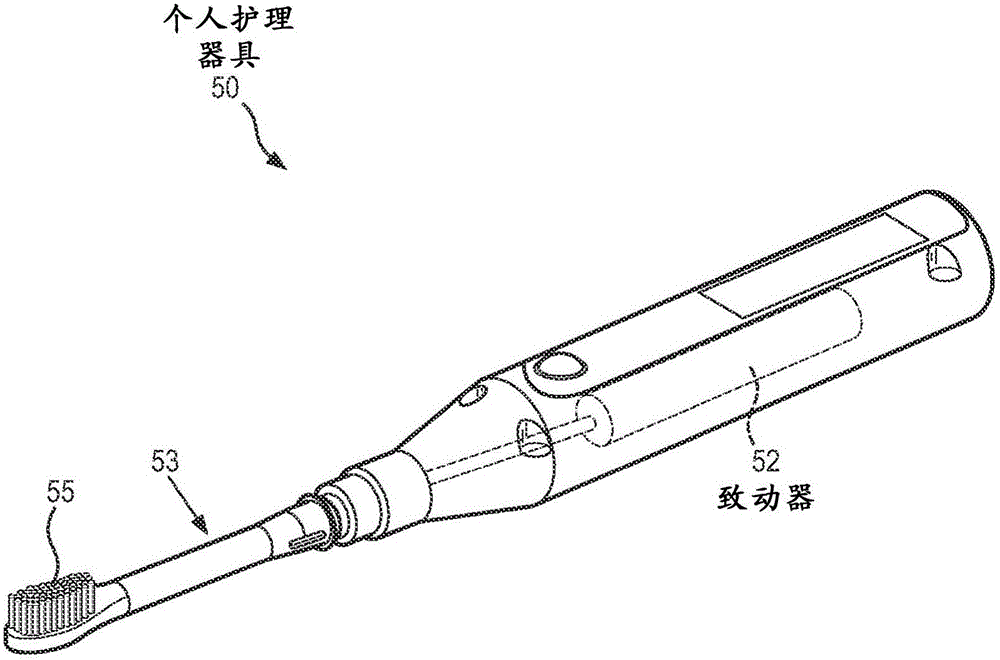
[0044] Embodiments and various features of the present disclosure and advantageous details thereof will be described more fully with reference to the non-limiting examples illustrated and / or illustrated in the accompanying drawings and detailed in the following description. It should be noted that the features illustrated in the figures are not necessarily drawn to scale and that features of one embodiment may be employed with other embodiments, as the skilled artisan will recognize, even if not explicitly stated herein. Descriptions of well-known components and processing techniques may be omitted so as not to unnecessarily obscure the embodiments of the present disclosure. The examples used herein are merely intended to facilitate an understanding of the manner in which embodiments of the present disclosure may be practiced and to further enable those skilled in the art to practice embodiments of the present disclosure. Thus, the examples herein should not be construed to li...


PUM


Abstract

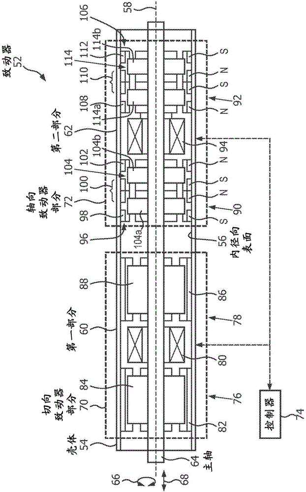
The invention discloses an actuator (52) for a personal care appliance (50). The actuator comprises a housing (54), a spindle (64), a tangential actuator portion (70), and an axial actuator portion (72). The tangential actuator portion (70) includes first and second magnet and pole assemblies (76, 78) that define a tangential spring function of the tangential actuator portion. The axial actuator portion (72) includes third and fourth magnet and pole assemblies (90, 92) that define an axial spring function of the axial actuator portion. At least one of (i) the first and second magnet and pole assemblies (76, 78) of the tangential actuator portion (70) and (ii) third and fourth magnet and pole assemblies (90, 92) of the axial actuator portion are configured to enhance a corresponding spring function of the axial actuator portion or tangential actuator portion, respectively.

Description

technical field [0001] The present embodiments relate generally to drive systems for personal care appliances such as electric toothbrushes, and more particularly to combined tangential and axial motion drive systems with enhanced magnetic spring functionality. Background technique [0002] figure 1 is a cross-sectional view of a dual motion actuator 10 having a tangential actuator portion 12 and an axial actuator portion 14 in accordance with the prior art. Tangential actuator portion 12 and axial actuator portion 14 share the same housing 16 and shaft (or main shaft) 18 . figure 1 The left-hand portion of the illustration shows an end view of the actuator 10, and particularly the tangential actuator portion 12 as viewed from the left-hand end. figure 1 The right-hand portion of the illustration shows the other end view of the actuator 10, and in particular the axial actuator portion 14 as seen from the right-hand end. [0003] The tangential actuator portion 12 generall...

Claims


Application Information

Patent Timeline
Patent Type & Authority Applications(China)
IPC IPC(8): A61C17/32A61C17/34
Inventor P·J·巴克斯F·J·伯斯曼
Owner KONINKLJIJKE PHILIPS NV
Features
  • R&D
  • Intellectual Property
  • Life Sciences
  • Materials
  • Tech Scout
  • Unparalleled Data Quality
  • Higher Quality Content
  • 60% Fewer Hallucinations
Learn More