
A circulation structure of an injection molding machine

A technology of injection molding machine and front machine, which is applied in the field of circulation structure of injection molding machine, can solve problems such as production difficulties, and achieve the effect of preventing long-term heating and discoloration

Active Publication Date: 2018-05-15
HAITIAN PLASTICS MACHINERY GRP
View PDF5 Cites 0 Cited by
  • Summary
  • Abstract
  • Description
  • Claims
  • Application Information

AI Technical Summary

Problems solved by technology

For light-colored products, it is difficult to produce

Method used


Image

  • A circulation structure of an injection molding machine
  • A circulation structure of an injection molding machine

Examples


Embodiment Construction

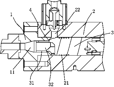
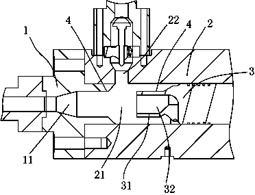
[0011] The present invention will be described in further detail below in conjunction with accompanying drawing and specific embodiment: see Figure 1 to Figure 2 , a circulation structure of an injection molding machine, comprising a front barrel 1 and a barrel 2, the front barrel 1 is provided with a feeding channel 11, the barrel 2 is provided with a plunger channel 21, and the plunger The channel 21 is connected with the feed channel 11, the plunger channel 21 is provided with a plunger 3, the side of the barrel 2 is provided with a feed port 22, and the top of the plunger 3 is provided with a diameter smaller than the inlet port. The boss 31 of the material channel 11, the plunger 3 and the boss 31 are provided with two openings located at the top of the boss 31 and a number of first passages 32 on the side walls of the plunger 3; when the boss When the head 31 fully extends into the feed channel 11 , the opening of the side wall of the plunger 3 communicates with the fee...


PUM


Abstract

The invention discloses a circulation structure of an injection molding machine. The circulation structure comprises a front machine barrel and a machine barrel. A feeding channel is arranged in the front machine barrel. A plunger channel is arranged in the machine barrel and connected with the feeding channel. A plunger is arranged in the plunger channel. A feeding port is formed in the side face of the machine barrel. A convex head with the diameter smaller than that of the feeding channel is arranged on the top of the plunger. The plunger and the convex head are provided with a plurality of first channels, wherein two openings of each first channel are located in the top of the convex head and the side wall of the plunger. When the convex head completely stretches into the feeding channel, the opening positions in the side wall of the plunger communicate with the feeding port through a gap between the plunger and the plunger channel. By means of the circulation structure of the injection molding machine, the outer side of a plunger head and the inner side of the front machine barrel can be prevented from accumulating raw materials for a long time, and therefore the situation that the raw materials change color due to long-time heating is prevented, and the double-order type injection molding machine can be suitable for manufacturing light-color products.

Description

technical field [0001] The invention belongs to the technical field of injection molding machines, in particular to a circulation structure of injection molding machines. Background technique [0002] For a two-stage structure injection molding machine, the parts where the molten plastic raw materials flow through are the most likely to accumulate material is the position of the plunger head and the front barrel. In the current structure, the melted plastic raw material flows in from the raw material channel on the side of the machine barrel, and will directly lead to the central hole of the front machine barrel. In this way, there are many parts on the outside of the plunger head that cannot produce a flushing effect. The inner side of the front barrel also has poor flushing effect. The raw materials in these parts will accumulate for a long time. And because of the production process, these parts are continuously heated. In this way, after a few hours or a few days, th...

Claims


Application Information

Patent Timeline
Patent Type & Authority Patents(China)
IPC IPC(8): B29C45/53
CPCB29C45/53
Inventor 张旭民何一帆
Owner HAITIAN PLASTICS MACHINERY GRP
Learn More