
Internal driving conveying belt for petroleum processing
A conveyor belt and internal drive technology, applied in the direction of conveyors, conveyor objects, conveyor control devices, etc., can solve problems such as large volume, achieve high transmission efficiency, strong carrying capacity, and long continuous operation life.
- Summary
- Abstract
- Description
- Claims
- Application Information
AI Technical Summary
Problems solved by technology
Method used
Image

Examples
Embodiment 1
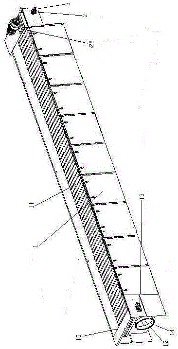
[0032]Embodiment one, see figure 1 , an internally driven conveyor belt for oil processing, including a frame 1 and a driving mechanism 4.
[0033] The frame 1 is provided with an endless conveyor belt 11 and a liquid storage chamber 12 . The liquid storage chamber 12 is located inside the space surrounded by the conveyor belt 11 . The left end of the liquid storage cavity 12 is provided with a liquid discharge port 14 . The front and rear left ends of the conveyor belt 11 are all provided with baffle plates 15 . The conveyor belt 11 is a conveyor belt provided with meshes, and the meshes on the conveyor belt communicate with the liquid storage chamber 12 . That is, the oil dripped on the conveyor belt 11 flows into the liquid storage chamber 12 under the action of gravity.
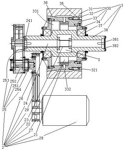
[0034] The frame 1 is also provided with a main drive shaft 3 and a slave drive shaft 13 . The main drive shaft 3 and the slave drive shaft 13 are arranged at both ends of the conveyor belt 11, and t...
Embodiment 2
[0041] Embodiment two, the difference with embodiment one is:
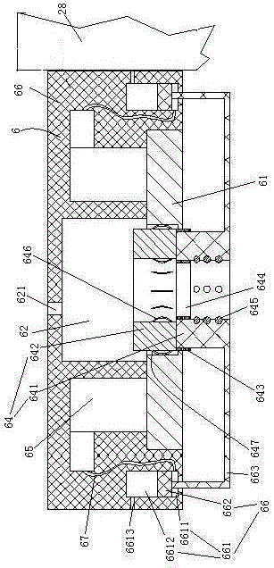
[0042] see image 3 , The motor 28 is provided with a connection terminal 6 . The connection terminal 6 includes an insulator 63 and a connection copper foil 61 disposed on the surface of the insulator. The insulator 63 is fixedly connected with the casing of the motor 28 . The wiring copper foil 61 is electrically connected with the coil of the motor. The wiring copper foil 61 is provided with a wiring hole 62 . The connection hole 62 penetrates into the insulator 63 . The wiring hole 62 is a blind hole with a closed upper end extending in the vertical direction. The wiring copper foil 61 is located at the lower end of the wiring hole 62 , that is, the opening end. A wiring sleeve 64 is slidably connected to the wiring hole 62 . The wire sleeve 64 includes an insulating segment 641 and a conductive segment 642 . The insulating segment 641 and the conductive segment 642 are axially distributed along the wi...
Embodiment 3
[0046] Embodiment three, the difference with embodiment two is:
[0047] see Figure 5 , the main shaft 38 is detachably connected with two board seats 383 distributed along the axial direction of the main shaft. The planetary gear 32 is rotatably connected between the two sockets 383 .
PUM
 Abstract
Description
Claims
Application Information