Thin strip lap welding method of lap welding machine of cold rolling recoiling unit

A lap welding and unit technology, which is applied in the field of steel rolling production, can solve the problem that the rewinding wire welder cannot effectively weld thin strips, etc., and achieves the effect of reducing the rewelding time and improving the production efficiency.

Active Publication Date: 2019-06-14
LIUZHOU IRON & STEEL
View PDF9 Cites 0 Cited by
  • Summary
  • Abstract
  • Description
  • Claims
  • Application Information

AI Technical Summary

Problems solved by technology

[0003] The purpose of the present invention is to provide a kind of lap-welding thin strip below 0.5mm thickness, which is economical and feasible, so as to solve the problem that the existing heavy coil welding machine cannot effectively weld the thin strip below 0.5mm thickness, and improve the unit production. Efficiency, yield and quality of cold rolling and recoiler lap welding machine thin strip lap welding method

Method used


Image

  • Thin strip lap welding method of lap welding machine of cold rolling recoiling unit
  • Thin strip lap welding method of lap welding machine of cold rolling recoiling unit
  • Thin strip lap welding method of lap welding machine of cold rolling recoiling unit

Examples


Embodiment Construction

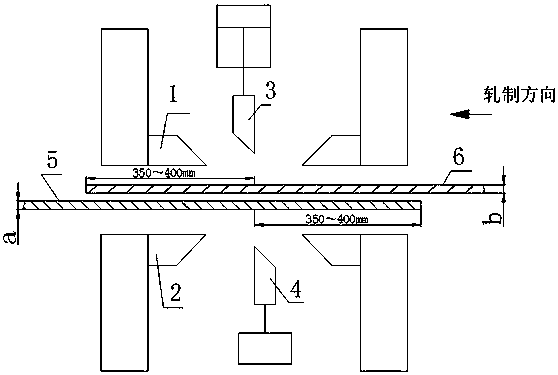
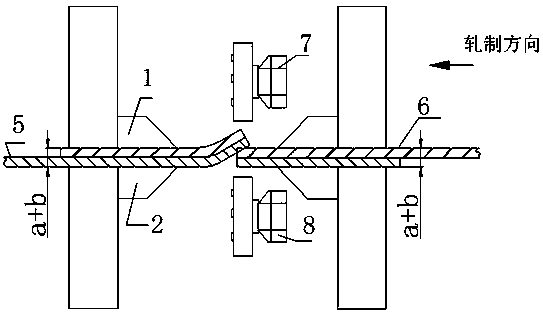
[0015] Attached below figure 1 , 2 The present invention is described in detail:

[0016] The specific operation steps are as follows:

[0017] 1. Use two rolls of strip steel at the front and back as superimposed raw materials: when the thickness a of the online steel coil is flicking, send the strip tail to a place about 350mm to 400mm from the edge of the lower clamp at the entrance of the welding machine, and do not enter the cutting edge; the next Coil thickness b When coiling up, the lead passes through the tail of the steel coil on the line, the lead passes through the lower shear blade of the welding machine, and enters the lower clamp of the welder exit with a length of about 350mm to 400mm (see figure 1 ).

[0018] 2. Use the built-in scissors of the welding machine to cut the head and tail: after the head and tail are aligned manually or automatically, the cutting operation is performed. At this time, there are two plates clamped in the welding machine’s output a...


PUM


Abstract

The invention discloses a method for achieving stitch welding of a thin strip by means of a lap welder of a cold rolling rewinding unit. The method comprises the steps that during tail flicking of an online steel coil with the thickness being a, a strip tail is conveyed to the place 350 mm-400 mm away from the edge of a lower clamp at an inlet of the welder and does not enter a shear blade; during coil feeding of a next steel coil with the thickness being b, a strip head passes through the strip tail of the online steel coil, and the strip head is conveyed through a lower shear blade of the welder and enters a lower clamp at an outlet of the welder by about 350 mm-400 mm; and after the strip head and the strip tail are aligned, built-in scissors of the welder are used for shearing the strip head and the strip tail for shear operation, the thickness of a front steel plate and a rear steel plate is changed into a+b after shearing is finished, and lap welding is carried out according to the parameter that the thickness of the steel strip is a+b after overlapping. The method has the beneficial effects that stable welding production of the ultra-thin strip is achieved; the need of cold rolling rewinding production is met; the rewelding time is shortened; production efficiency is improved; the rewelding rate is reduced to 2% from original 83%; and the strip breakage rate is also reduced to 0.

Description

technical field [0001] The invention relates to the field of iron and steel rolling production, in particular to a method for lap welding thin strips with a thickness of less than 0.5 mm by lap welding machines in cold rolling plants. Background technique [0002] At present, in the production of cold rolling and recoiling units, when welding thin strip steel with a thickness of less than 0.5mm, it is difficult to ensure the quality of the weld seam due to the thin strip material, and welding according to the process parameters is easy to produce virtual welding, desoldering, and penetration. Welding, the strength of the weld seam cannot be guaranteed, and the weld seam is easily broken when it passes through the process section and the tension is built, and the forward production of the recoiling line cannot be guaranteed. With the transition plate welding, a steel plate of about 0.8mm×350mm is added in the middle of the lap welding strip for transition welding. Although th...

Claims


Application Information

Patent Timeline
Patent Type & Authority Patents(China)
IPC IPC(8): B23P23/04B23K31/02
CPCB23K31/02B23P23/04
Inventor 彭仕军吴兵凌应勇蒋才灵何精斌辛枫
Owner LIUZHOU IRON & STEEL
Why Eureka
Try Eureka