A transfer box structure

A box structure and frame technology, which is applied in the transportation of passenger cars, transportation and packaging, railway car body parts, etc., can solve the problems of battery heat dissipation, easy discharge and heat generation of batteries, power supply damage and liquid leakage, etc., to reduce vibration impact The effect of transmission, ensuring service life and improving heat dissipation effect

Inactive Publication Date: 2018-08-28
ZHEJIANG SCI-TECH UNIV
View PDF6 Cites 0 Cited by
  • Summary
  • Abstract
  • Description
  • Claims
  • Application Information

AI Technical Summary

Problems solved by technology

[0002] At present, during the transfer process of the battery, it is usually transported in a transfer box. After the battery is manufactured, it is usually charged. During the transportation process, it is subject to vibration. The battery is also prone to discharge and heat due to internal resistance, which makes the power supply prone to damage and leakage. The situation will affect the stable power output of the power supply, making it difficult to guarantee the service life of the power supply
At present, the battery mainly dissipates heat to the outside through the casing. When there are a large number of densely packed batteries in the box, the heat generated will also increase greatly, causing the box to have no time to dissipate the heat generated by the battery. Elevated, affecting the safety and service life of the battery

Method used


Image

  • A transfer box structure
  • A transfer box structure
  • A transfer box structure

Examples


Embodiment Construction

[0019] The present invention will be further described below in conjunction with the accompanying drawings and specific embodiments.

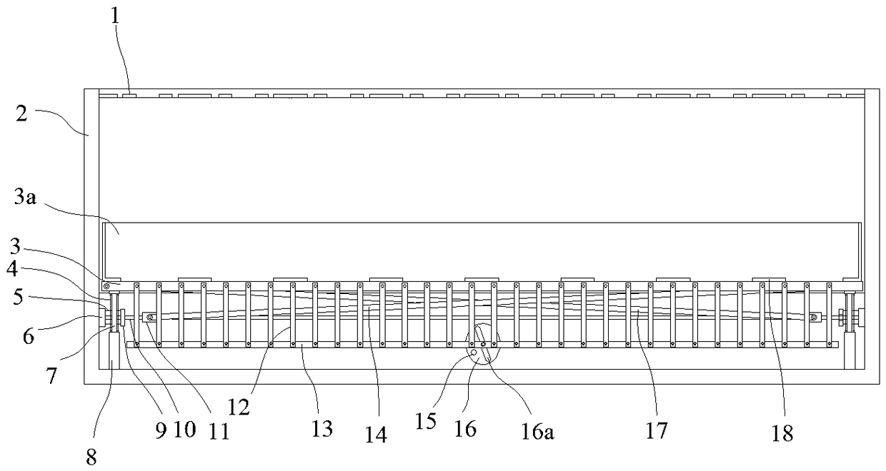
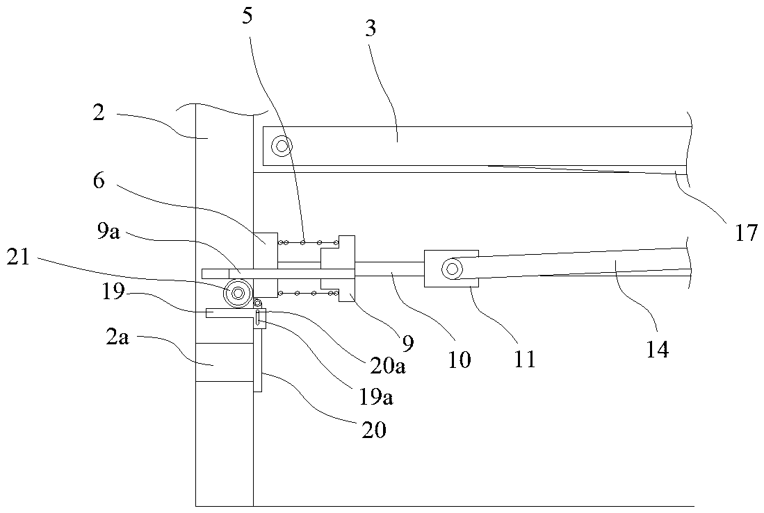
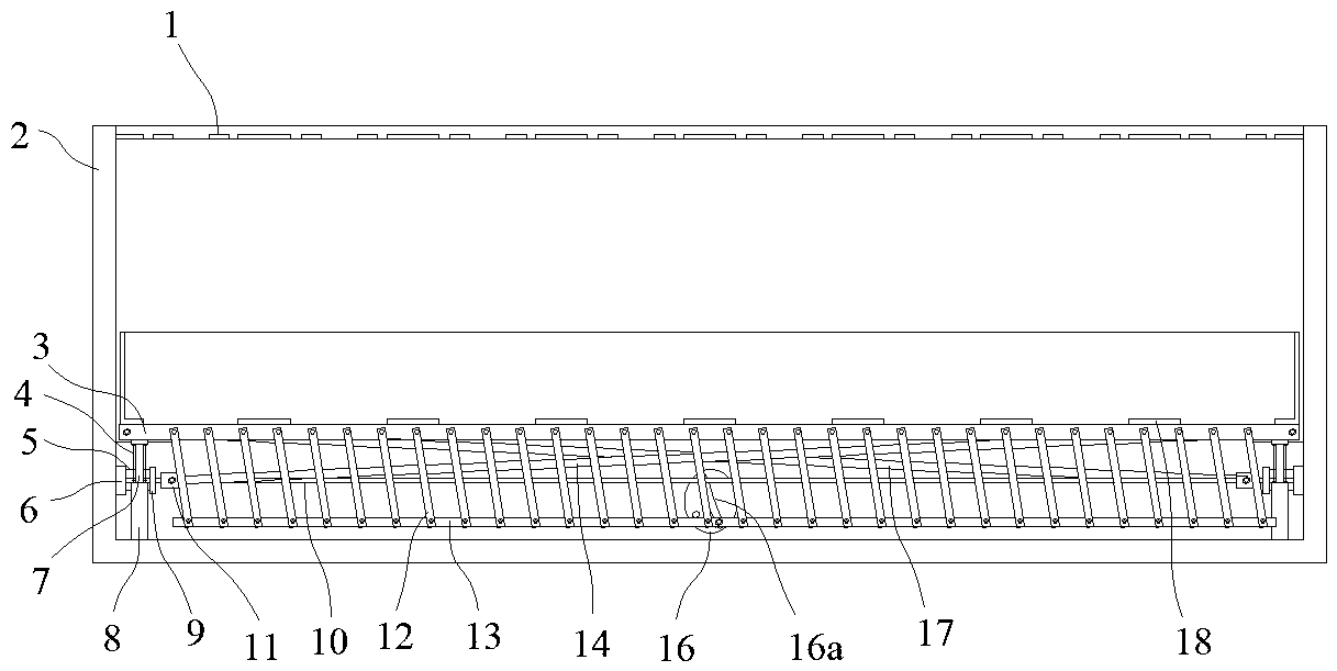
[0020] like figure 1 In the shown embodiment, a transfer box structure includes an outer casing 2, the top of the battery casing is provided with a number of upper vents 1 set to the side, and a shock-absorbing frame 3 is arranged in the outer casing, and the shock-absorbing frame The lower end is provided with a vertically arranged guide column 7, and the inner bottom of the outer shell is provided with a guide sleeve 8. The guide column and the guide sleeve are slidably matched so that the shock-absorbing frame can move up and down in the outer shell, and the guide column is provided with a shock-absorbing spring. 4. When the shock-absorbing frame moves down, the shock-absorbing spring will be compressed. The battery is arranged on the shock-absorbing frame, and the edge of the upper surface of the shock-absorbing frame is provided with an o...


PUM


Abstract

The invention discloses a transfer box structure which comprises an outer shell. A damping frame capable of moving up and down is arranged in the outer shell. Damping springs are arranged between the damping frame and the bottom of the outer shell. A plurality of parallel cooling fins are arranged on the lower portion of the damping frame and rotatably connected with the damping frame. Horizontal sliding grooves and sliding blocks in sliding fit with the sliding grooves are formed in and arranged on the inner walls of the outer shell. The damping frame is provided with a supporting rack capable of pushing the sliding blocks to move along the sliding grooves. A driven rack rotatably connected with the cooling fins is arranged under the damping frame. An oblique groove is formed in the outer shell and used for driving the driven rack to move in the horizontal direction when the driven rack vertically moves, a sliding pin in sliding fit with the oblique groove is arranged on the driven rack, and an outer baffle is arranged on the edge of the upper surface of the damping frame. Buffer blocks are arranged at the two ends of the oblique groove correspondingly. The ventilation and heat dissipation capacity of the transfer box structure can be improved.

Description

technical field [0001] The invention belongs to the field of transfer boxes, in particular to a transfer box structure. Background technique [0002] At present, during the transfer process of the battery, it is usually transported in a transfer box. After the battery is manufactured, it is usually charged. During the transportation process, it is subject to vibration. The battery is also prone to discharge and heat due to internal resistance, which makes the power supply prone to damage and leakage. The situation affects the stable power output of the power supply, making it difficult to guarantee the service life of the power supply. At present, the battery mainly dissipates heat to the outside through the casing. When there are a large number of densely packed batteries in the box, the heat generated will also increase greatly, causing the box to have no time to dissipate the heat generated by the battery. It will affect the safety and service life of the battery. Cont...

Claims


Application Information

Patent Timeline
Patent Type & Authority Patents(China)
IPC IPC(8): B65D88/74B65D90/00
CPCB65D88/742B65D90/00
Inventor 孙永剑喻海清
Owner ZHEJIANG SCI-TECH UNIV
Why Eureka
Try Eureka