
A drill rod displacement trigger mechanism for a breaking hammer

A technology of triggering mechanism and breaking hammer, which is applied in the direction of earth mover/shovel, mechanically driven excavator/dredger, road, etc., can solve the problems such as the inability to release the kinetic energy of beating, the damage of the drill rod, and the increase of equipment operating costs.

Active Publication Date: 2018-08-03
纵驰电子科技(南通)有限责任公司
View PDF7 Cites 2 Cited by
  • Summary
  • Abstract
  • Description
  • Claims
  • Application Information

AI Technical Summary

Problems solved by technology

[0002] At present, the breaker has various drive modes such as hydraulic drive, nitrogen drive, nitrogen and hydraulic drive, gravity drive, etc. Each drive mode is achieved by hitting the drill rod at high speed so that the drill rod has a large kinetic energy in an instant to achieve crushing. The effect of the object; when the chisel is hit, the huge kinetic energy is released by breaking the object, but the chisel is often separated from the object during work, and the beating is still in progress at this time, and the huge beating kinetic energy cannot be released. Hitting will cause great damage to the drill rod, resulting in increased equipment operating costs

Method used


Image

  • A drill rod displacement trigger mechanism for a breaking hammer
  • A drill rod displacement trigger mechanism for a breaking hammer
  • A drill rod displacement trigger mechanism for a breaking hammer

Examples


Embodiment Construction

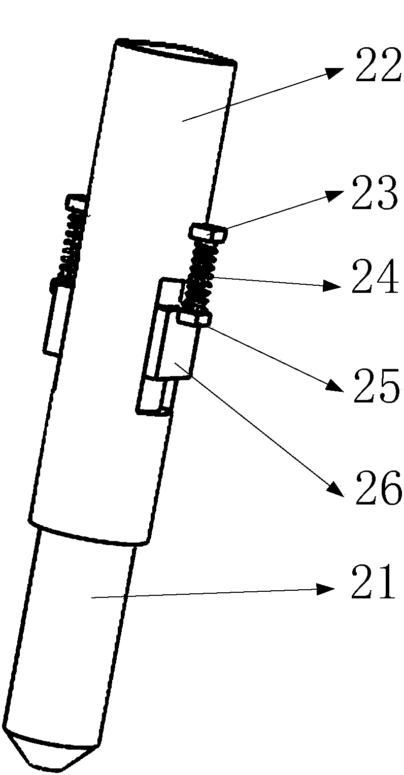
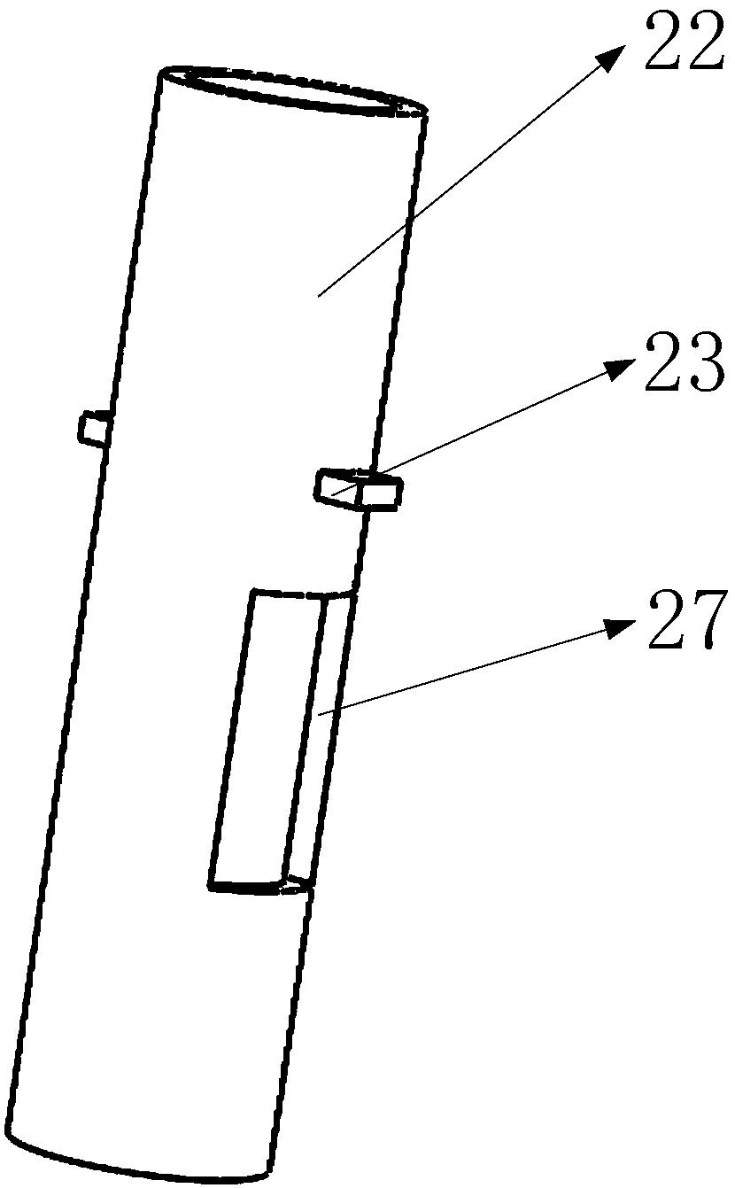
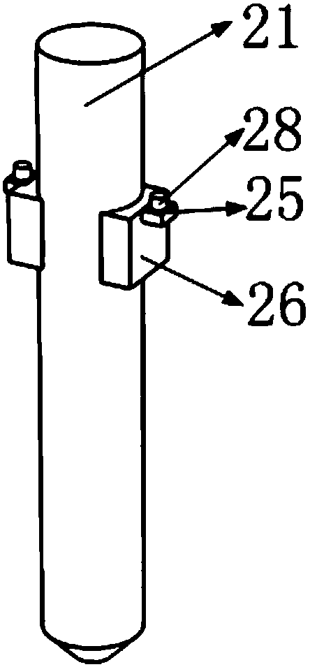
[0021] Such as Figure 4 As shown, it includes driving slider, limit block, guide rail, first support plate, amplitude valve body, first valve block, hydraulic hole, second valve block, third valve block, fourth valve block, second support plate, drive chute, valve body chute, valve body shell, third support plate, valve body spring, drill rod, drill rod sleeve, first drill rod spring support, drill rod spring, second drill rod spring support, drill rod Rod guide block, drill rod sleeve sliding hole, spring pin, such as figure 2 As shown, there is a drill rod sleeve sliding hole in the lower part of the drill rod sleeve and runs through the entire drill rod sleeve. The two first drill rod spring supports are symmetrically installed on the drill rod sleeve and are located on the upper side of the drill rod sleeve slide hole. ,Such as image 3 As shown, two drill rod guide blocks are installed symmetrically in the middle of the drill rod, and a second drill rod spring support...


PUM


Abstract

The invention belongs to the technical field of breaking hammers and particularly relates to a drill rod displacement triggering mechanism for a breaking hammer. The drill rod displacement triggering mechanism comprises a drive sliding block, a limiting block, a range valve body, hydraulic holes, a valve body shell, a valve body spring, a drill rod, a drill rod sleeve and drill rod springs. The drill rod is installed in the drill rod sleeve through sliding fit of drill rod guide blocks and drill rod sleeve sliding holes. The drill rod springs are installed on the guide blocks. When the drill rod works in a reciprocating knocking manner, a drill rod reset effect is achieved. The valve body shell is installed on the drill rod sleeve through a first supporting board, a second supporting board and a third supporting board. The range valve body is installed on the valve body shell. The valve body spring is installed between the range valve body and the third supporting board. In the drill rod displacement triggering mechanism, only when the drill rod applies certain force to an object and the drill rod retracts inwards can an oil way be opened and a knocking mechanism be started; and the knocking mechanism stops knocking immediately as soon as the drill rod gets away from the object, a drill rod idling phenomenon is prevented, and the service life of the drill rod is prolonged. The mechanism has the good use effect.

Description

Technical field [0001] The invention belongs to the technical field of breaking hammers, and in particular relates to a drill rod displacement triggering mechanism of a breaking hammer. Background technique [0002] At present, the breaker has various drive modes such as hydraulic drive, nitrogen drive, nitrogen and hydraulic drive, gravity drive, etc. Each drive mode is achieved by hitting the drill rod at high speed so that the drill rod has a large kinetic energy in an instant to achieve crushing. The effect of the object; when the chisel is hit, the huge kinetic energy is released by breaking the object, but the chisel is often separated from the object during work, and the beating is still in progress at this time, and the huge beating kinetic energy cannot be released. Hitting will cause great damage to the drill rod, resulting in increased equipment operating costs. [0003] The present invention designs a drill rod displacement trigger mechanism of the breaker on th...

Claims


Application Information

Patent Timeline
Patent Type & Authority Patents(China)
IPC IPC(8): E01C23/12E02F3/96
CPCE01C23/124E02F3/966
Inventor 朱敏
Owner 纵驰电子科技(南通)有限责任公司
Learn More