Working principle of electronic percussion instrument

A technology of percussion instruments and working principles, applied in the direction of electroacoustic musical instruments, instruments, etc., can solve the problems of single and high performer requirements

Inactive Publication Date: 2016-10-12
MEET STUDIO
View PDF5 Cites 2 Cited by
  • Summary
  • Abstract
  • Description
  • Claims
  • Application Information

AI Technical Summary

Problems solved by technology

[0002] Traditional musical instruments have high requirements

Method used


Image

  • Working principle of electronic percussion instrument
  • Working principle of electronic percussion instrument
  • Working principle of electronic percussion instrument

Examples


Embodiment 1

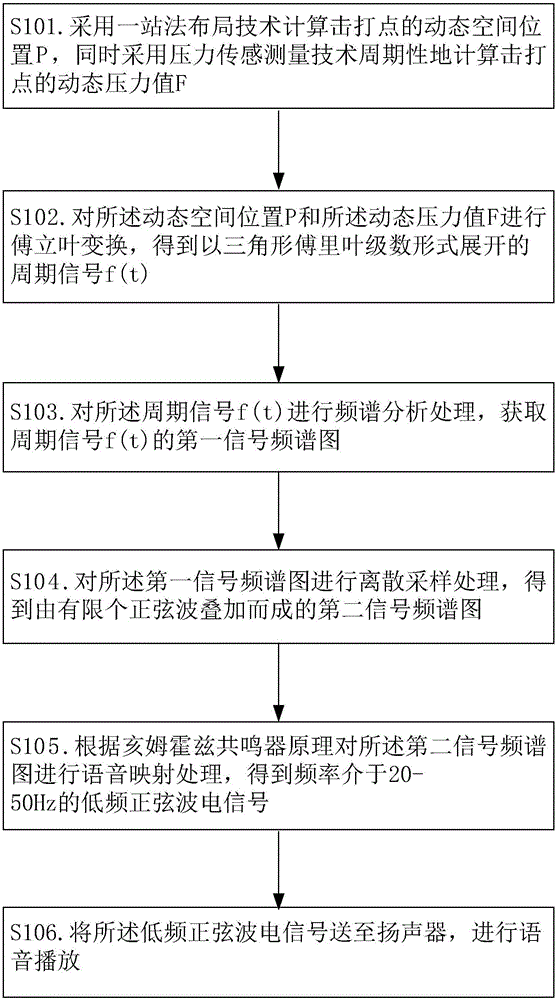
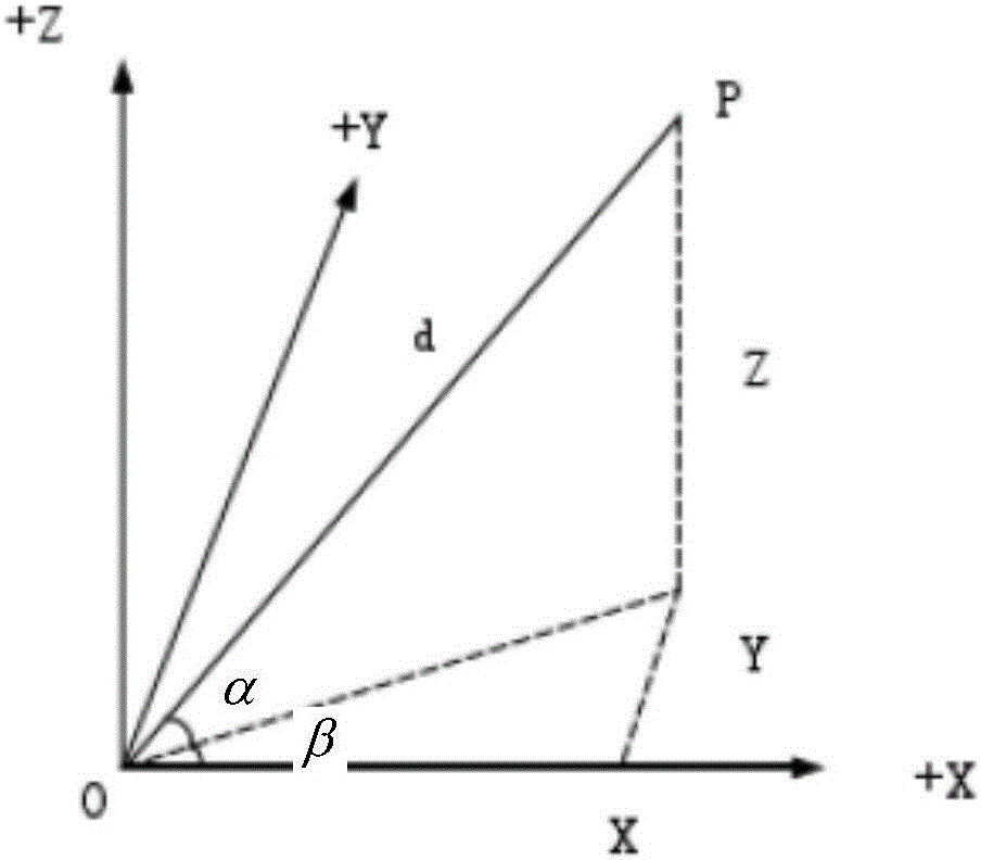
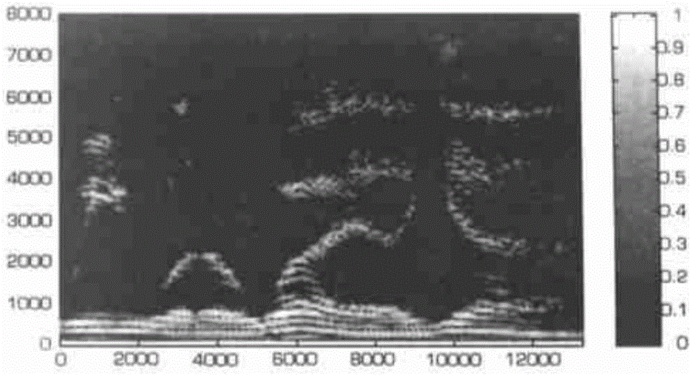
[0035] figure 1 It shows the flow chart of the working principle of the electronic percussion instrument provided by the present invention, figure 2 The one-stop method measurement mathematical model in the working principle of the electronic percussion instrument provided by the present invention is shown, image 3 It shows the signal dynamic spectrogram of a sentence of speech in the working principle of the electronic percussion instrument provided by the present invention using the Matlab system to realize the signal spectrum analysis and display method. The working principle of the electronic percussion instrument provided in this embodiment includes the following steps.

[0036] S101. Calculate the dynamic spatial position P of the hitting point by using the one-stop method layout technology, and at the same time use the pressure sensing measurement technology to periodically calculate the dynamic pressure value F of the hitting point.

[0037] In step S101, the metho...


PUM


Abstract

The invention relates to the field of music instrument equipment, and discloses a working principle of an electronic percussion instrument. Based on the working principle of the electronic percussion instrument, the percussion rate of a user and the X/Y-axis offset of percussion keys can be measured according to dynamic space position and pressure, a corresponding signal frequency spectrogram can be obtained through Fourier series transform, and finally, a sound of which the frequency is 20-50Hz is produced under the mapping action of a Helmholtz resonator. The working principle can be applied to music creation, instrument playing practice and other scenes, and plays a huge role in the fields of music enlightenment education and music therapy.

Description

technical field [0001] The invention relates to the field of musical instruments, in particular to the working principle of an electronic percussion instrument. Background technique [0002] Traditional musical instruments have higher requirements for players, and can only play the sound of a single musical instrument. It takes years of professional study before people can play a certain instrument with ease. But for ordinary amateur music lovers, an instrument that is easy to operate and can play a variety of music is the best solution to meet their needs. Contents of the invention [0003] In view of the above-mentioned problems of the current traditional musical instrument equipment, the present invention provides a working principle of an electronic percussion instrument, which can measure the user's hitting speed and the offset of the X / Y axis on the hitting key according to the dynamic space position and pressure, The corresponding signal spectrum is obtained throu...

Claims


Application Information

Patent Timeline
IPC IPC(8): G10H3/12
CPCG10H3/12G10H2250/235
Inventor 刘德文阮广璇陈洪波
Owner MEET STUDIO
Why Eureka
Try Eureka