A kind of power original locking installation equipment

A technology for installing equipment and components, applied in the field of electric component locking and installation equipment, can solve the problems of inconvenient disassembly, aging bolt structure, small space inside the instrument box, etc., and achieve the effect of convenient installation, locking and laying.

Active Publication Date: 2018-12-18
扬中市新坝科创服务有限公司
View PDF3 Cites 0 Cited by
  • Summary
  • Abstract
  • Description
  • Claims
  • Application Information

AI Technical Summary

Problems solved by technology

[0002] During the installation process of existing electrical equipment and original components, bolts and other connection methods are mainly used. Due to the small internal space of instrument boxes, instruments of different sizes need to be installed or fixed in special instrument boxes, and in order to facilitate installation, usually Bolts are used for fixed installation, and the bolts and other structures are prone to aging, resulting in inconvenient disassembly

Method used


Image

  • A kind of power original locking installation equipment
  • A kind of power original locking installation equipment

Examples


Embodiment 1

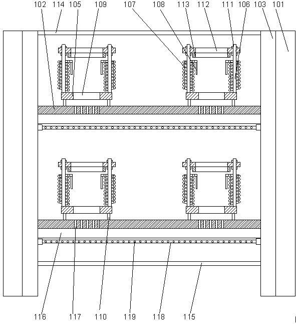
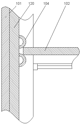
[0019] Such as figure 1 As shown in / 2, a power element locking and installation device includes a mounting plate 101 and a support plate 102 arranged on the mounting plate 101. The two mounting plates 101 are oppositely arranged, and the two mounting plates 101 Mounting strips 103 are respectively provided on the opposite end faces, and the mounting strips 103 are parallel to the plane where the mounting plate 101 is located, and spaced positioning pieces 104 are arranged inside the mounting strips 103. The positioning piece 104 is made of two elastic metal sheets arranged up and down. The elastic metal sheet is in an arc-shaped structure arched toward the inside of the mounting plate 101, and the two ends of the elastic metal sheet located at the lower part are fixedly connected. On the described installation strip 103, the lower end of the elastic metal sheet positioned at the upper part is fixedly connected to the described installation strip 103, and its upper end is susp...

Embodiment 2

[0024] In this embodiment, in order to facilitate installation, preferably, a stud 111 is provided on the upper end surface of the column 106, and an end cap 112 is arranged above the stud 111, and the end cap 112 is hollow and annular Structure, the four corners of the end cover 112 are respectively provided with through holes, and the upper ends of the studs 111 respectively pass through the corresponding through holes and are connected with the end cover 112 through nuts. By adopting the end cover structure, the upper end surface of the power meter can be protected. Due to the hollow ring structure, the display part or switch part of the electric meter can be relatively suspended inside the hollow structure of the end cover, which is convenient for operation and observation.

[0025] In this embodiment, in order to prevent the upper end of the instrument from colliding with the end cover when vibration occurs, preferably, an annular buffer pad 113 is provided on the lower e...

Embodiment 3

[0028] In this embodiment, in order to facilitate the laying of lines, preferably, a wiring groove 116 is provided on the lower end surface of the support plate 102, and a wiring hole communicating with the wiring groove 116 is provided on the support plate 102 117.

[0029] The lines connected to the instruments can be laid through the wiring troughs, so that the lines can be connected to the line adapter board through the wiring troughs and wiring holes, which facilitates the classified connection of the lines, thus facilitating the maintenance and management of different instruments in the overall structure.


PUM


Abstract

The invention discloses a power component locking and installing equipment which comprises two mounting plates and support plates arranged on the mounting plates. The two mounting plates are arranged face to face. The facing end faces of the two mounting plates are provided with mounting strips which are perpendicular to the plane where the mounting plates are located. The inner sides of the mounting strips are provided with positioning pieces arranged with intervals. Each of the positioning pieces is formed by two elastic metal pieces in an up and down arrangement. The elastic metal pieces are curved structures which are arched to the inner sides of the mounting plates. Two ends of the elastic metal piece at the lower part are fixedly connected to the mounting strips, and the lower end of the elastic metal piece at the upper part is fixedly connected to the mounting strips. According to the invention, through using the elastic positioning piece structures, the installation and height adjustment of the support plates are realized, at the same time a torsion spring is used to form the cavity for clamping an instrument, the power component locking and installing equipment can be conveniently used for the installation and fixation of instruments with multiple sizes, the structure is simple, and the application range is wide.

Description

technical field [0001] The invention relates to a device for locking and installing electric power components. Background technique [0002] During the installation process of existing electrical equipment and original components, bolts and other connection methods are mainly used. Due to the small internal space of instrument boxes, instruments of different sizes need to be installed or fixed in special instrument boxes, and in order to facilitate installation, usually Bolts are used for fixed installation, and structures such as bolts are prone to aging, resulting in inconvenient disassembly. Contents of the invention [0003] The purpose of the present invention is to provide a device for locking and installing electric power components, which can improve the problems existing in the prior art. By adopting an elastic positioning piece structure, the installation of the support plate and the adjustment of the height can be realized. The cavity can be conveniently used f...

Claims


Application Information

Patent Timeline
Patent Type & Authority Patents(China)
IPC IPC(8): H05K7/14
CPCH05K7/14
Inventor 季翠娜杨世盛王德刚丁镇张道升于凤举张轩焜张远铭孙世军张通永王兵王斌郝先廷张志王名科姜浩
Owner 扬中市新坝科创服务有限公司
Why Eureka
Try Eureka