Butt joint chip removal groove

A chip flute and sub-groove technology, used in metal processing machinery parts, maintenance and safety accessories, metal processing equipment, etc., can solve problems such as poor sealing of joints, large pollution of cutting fluid, and harsh workshop environment, and achieve production Low cost, long service life, and the effect of ensuring tightness

Active Publication Date: 2015-10-21
FOSHAN PRATIC CNC SCI & TECH
View PDF5 Cites 0 Cited by
  • Summary
  • Abstract
  • Description
  • Claims
  • Application Information

AI Technical Summary

Problems solved by technology

[0002] In the existing large-scale processing machine tools, the drainage and chip removal mechanism is made of castings, with a length of more than 10 meters and a solid design. The cost of forming, baking and transportation of the entire drainage

Method used


Image

  • Butt joint chip removal groove
  • Butt joint chip removal groove
  • Butt joint chip removal groove

Examples


Embodiment Construction

[0020] The technical solutions of the present invention will be further described below in conjunction with the accompanying drawings and through specific implementation methods.

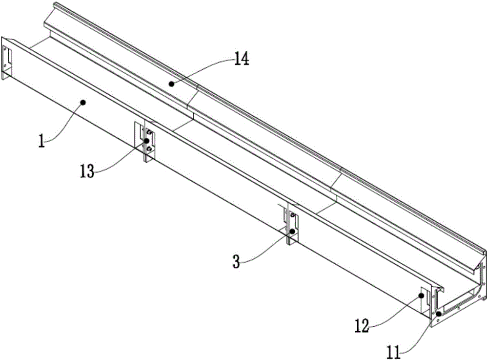
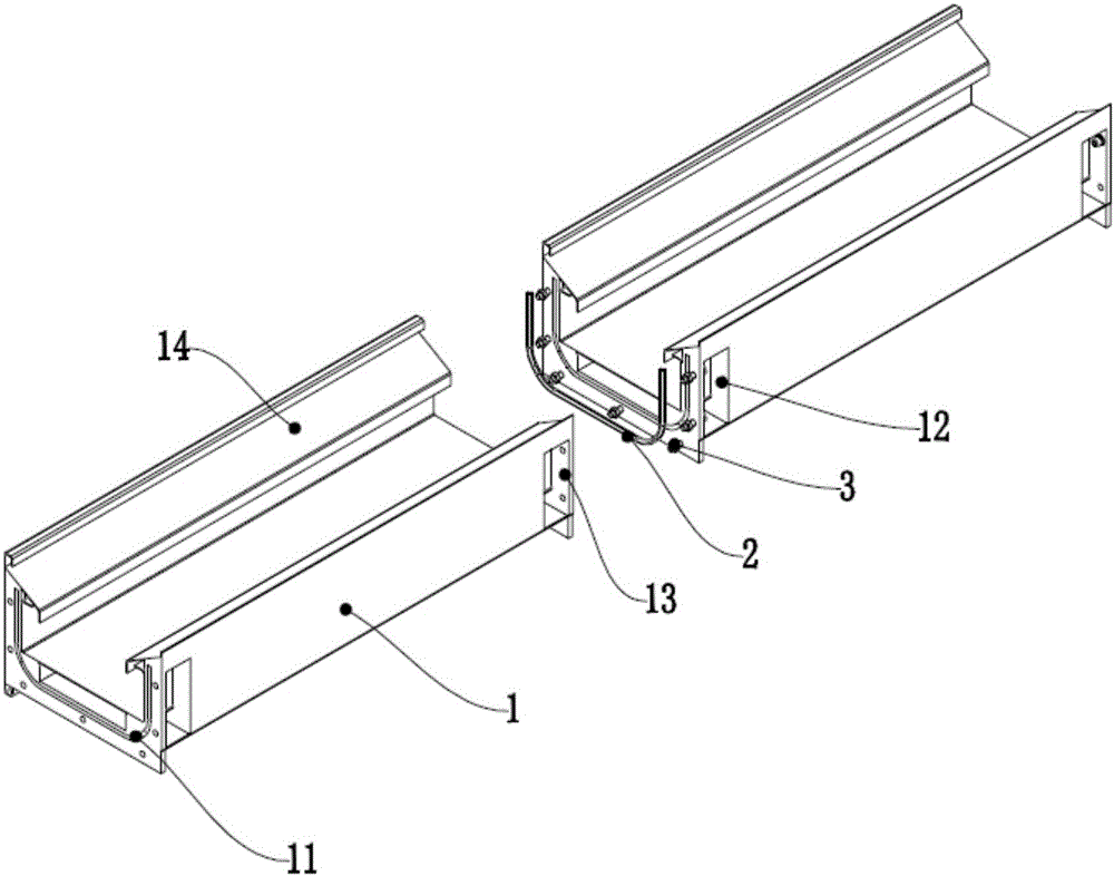
[0021] A butt joint chip removal flute, which is assembled from multiple chip removal sub-grooves 1. The chip removal sub-grooves 1 are U-shaped groove structures with an upward opening, and the assembly surfaces of the chip removal sub-grooves 1 are symmetrically arranged. The U-shaped grooves 11 are sealed and connected between adjacent chip removal sub-grooves 1 through the sealing strip 2 embedded in the above-mentioned U-shaped grooves 11 .

[0022] The drainage chip removal groove is assembled by multi-section chip removal sub-grooves 1, which is easy to install, simplifies the structure, and reduces the cost. The adjacent chip removal sub-grooves 1 are sealed and connected by the sealing strip 2 embedded in the U-shaped groove 11. When installing, the sealing strip 2 is nested and installed i...


PUM


Abstract

The invention provides a butt joint chip removal groove. The butt joint chip removal groove is formed by splicing multiple sections of chip removal branch grooves. The chip removal branch grooves are each of a U-shaped groove type structure with an upward opening. U-shaped grooves are symmetrically formed in the splicing faces of the chip removal branch grooves. The adjacent chip removal branch grooves are connected in a sealed mode through sealing strips embedded into the U-shaped grooves. The spliced butt joint chip removal groove with the good sealing effect is provided. The sealing performance of segmented splicing portions is guaranteed through embedding installation of compressive deformation of the sealing strips and the compact connection mode of the sealing strips; the tidy working environment is kept; installation is easy and convenient; production cost is low.

Description

technical field [0001] The invention relates to the technical field of chip removal for processing machine tools, in particular to a butt chip removal groove. Background technique [0002] In the existing large-scale processing machine tools, the drainage and chip removal mechanism is made of castings, with a length of more than 10 meters and a solid design. The cost of forming, baking and transportation of the entire drainage and chip removal structure is very high, and the joint is not well sealed and often leaks out of the chip. The liquid pollution is large, resulting in water everywhere in the workshop, resulting in a bad environment in the workshop. Not easy to install. Therefore, it is necessary to improve the structure of its drainage and chip removal. Contents of the invention [0003] The purpose of the present invention is to propose a butt chip flute which is assembled and has a good sealing effect. Through the nested installation and tight connection of the ...

Claims


Application Information

Patent Timeline
IPC IPC(8): B23Q11/00
CPCB23Q11/0042
Inventor 叶永安李海东刘世泉
Owner FOSHAN PRATIC CNC SCI & TECH
Why Eureka
Try Eureka