
A Complicated Surface Polishing Device

A complex curved surface and polishing technology, which is applied in the direction of grinding/polishing safety devices, grinding drive devices, grinding/polishing equipment, etc., can solve the problems of difficult control, weakening, and unstable control, and achieve high polishing precision , good supple control, good control stability

Inactive Publication Date: 2020-12-22
NINGBO INST OF TECH ZHEJIANG UNIV ZHEJIANG
View PDF6 Cites 0 Cited by
  • Summary
  • Abstract
  • Description
  • Claims
  • Application Information

AI Technical Summary

Problems solved by technology

This force / position hybrid control method is a strategy of time-varying strong coupling and highly nonlinear weakening. It is very difficult to realize the control of displacement-pose-force, with low precision and unstable control, and it is not suitable for processing complex surfaces. The position and posture of the robot cannot be actively controlled, and it cannot solve the contradiction between the high flexibility of generating arbitrary force required during polishing and the high rigidity of the position and structure of the robot itself during operation.

Method used


Image

  • A Complicated Surface Polishing Device
  • A Complicated Surface Polishing Device
  • A Complicated Surface Polishing Device

Examples


Embodiment 1

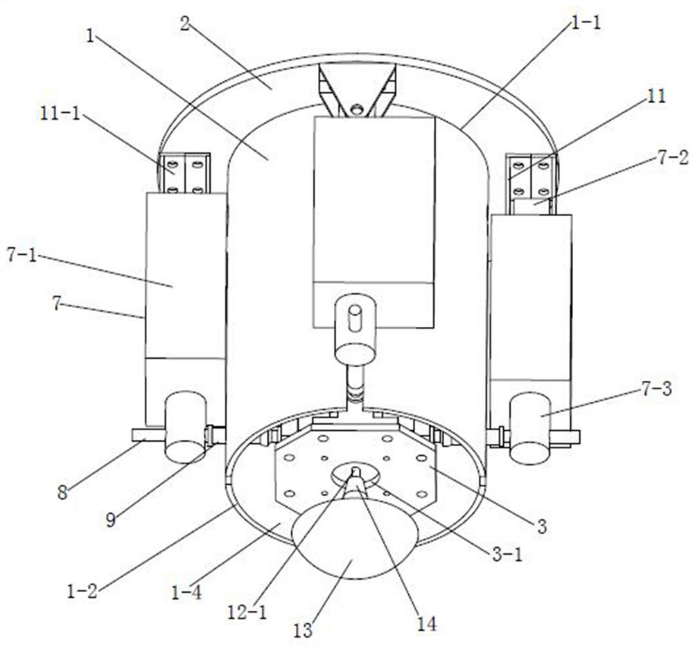
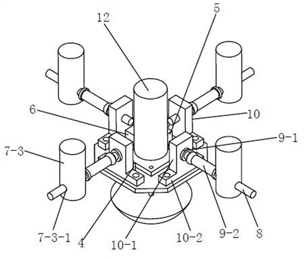
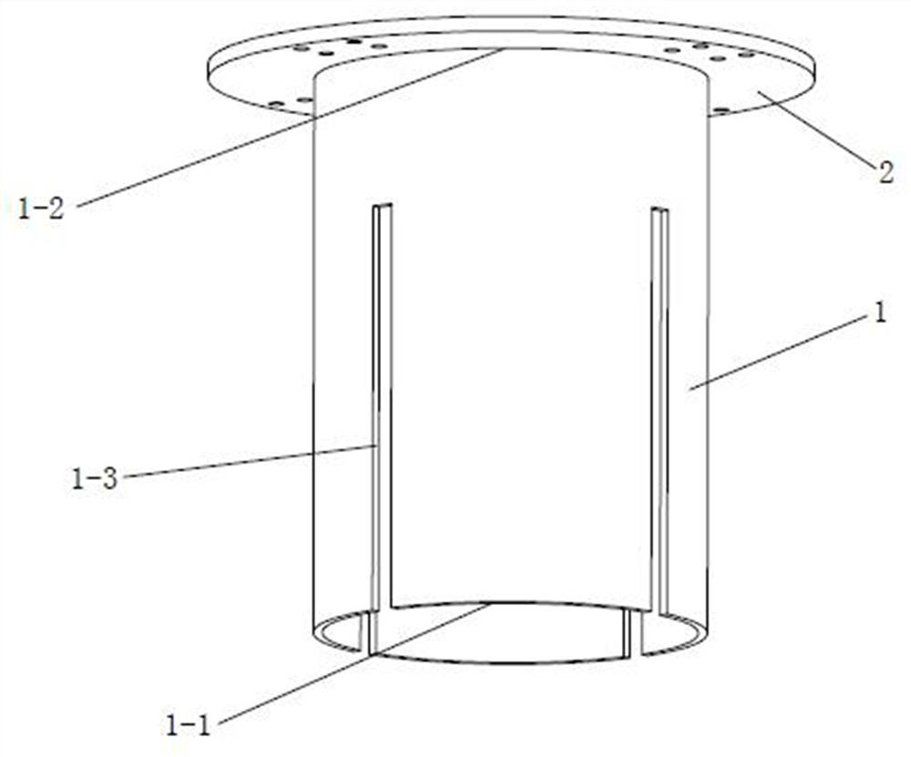
[0030] like Figure 1-3 As shown, a complex curved surface polishing device provided in this embodiment includes:

[0031] A circular tubular base 1 is provided with four grooves 1-3 evenly distributed around the center line on the side wall,

[0032] The four tanks 1-3 all extend from the first end 1-1 of the base 1 to the second end 1-2; a flange 2 is arranged on the outside of the second end 1-2, and the flange 2 directly welded to the second end 1-2, and the center lines of the flange 2 and the base 1 coincide;

[0033] A force position control device, including a substrate 3, a multidimensional force sensor 4, an inclination sensor 5, a controller 6, four servo electric push rods 7, four connecting rods 8, four ball joint bearings 9 and four A ball joint bearing seat 10; the center of the base plate 3 is provided with a first through hole 3-1;

[0034] Wherein, the substrate 3 is located on one side of the first end 1-1 of the base 1, and the four ball joint bearing se...

Embodiment 2

[0050] A kind of complex curved surface lapping and polishing device provided in this embodiment, its general structure is consistent with embodiment 1, as Figure 4 As shown, but in this embodiment, the side wall of the base 1 is provided with four installation reserved holes 1-5 uniformly distributed around the center line, and are connected with the fasteners on the four mounting seats 11 one by one. correspond.

[0051] The aforementioned installation reserved holes 1-5 can facilitate the locking and installation of the connecting head 7-2 of the servo electric push rod 7 and the mounting seat 11 through fasteners.


PUM


Abstract

The invention discloses a curved surface polishing device and particularly relates to a complex curved surface polishing device. The complex curved surface polishing device comprises a base, a polishing device and a force position control device, wherein a controller in the force position control device is used for taking updated position and posture of a polishing head as feedback, carrying out closed-loop control on an inclination angle of the polishing head, enabling the inclination angle of the polishing head to freely change in the wake of curvature of complex curved surfaces and adjusting the position and the posture of the polishing head in real time; in view of corresponding polishing force given values suitable for operation conditions of different curved surfaces, the controllerneeds to synchronously carry out closed-loop control on resultant force which is polishing force of the polishing device and is applied to the polishing head by four servo motor pushing rods in the above process, so that actual polishing force is freely changed in the wake of the given values, and the polishing force of the polishing device is accurately controlled. The complex curved surface polishing device is used for actually solving the technical problem that the polishing device achieves high-accuracy control on force and positions when polishing the complex curved surfaces, and has theadvantages of high compliance control stability and high polishing accuracy.

Description

technical field [0001] The invention relates to a curved surface polishing device, in particular to a complex curved surface polishing device. Background technique [0002] At present, in the compliant control of curved surface grinding and polishing operations, using automatic equipment such as robots instead of manual labor, it is more common to install passive compliant structures such as springs and dampers on the end effector and adopt the pose adaptive surface method to achieve compliant control. . This force / position hybrid control method is a strategy of time-varying strong coupling and highly nonlinear weakening. It is very difficult to realize the control of displacement-pose-force, with low precision and unstable control, and it is not suitable for processing complex surfaces. The pose cannot be actively controlled, and it cannot solve the contradiction between the high flexibility to generate arbitrary force required during polishing and the high rigidity of the...

Claims


Application Information

Patent Timeline
Patent Type & Authority Patents(China)
IPC IPC(8): B24B27/00B24B49/16B24B47/04B24B55/00B25J11/00
CPCB24B27/00B24B47/04B24B49/165B24B55/00B25J11/0065
Inventor 詹建明周思育胡利永王义强张慧娟高如君
Owner NINGBO INST OF TECH ZHEJIANG UNIV ZHEJIANG
Learn More