Hoop fastening device and method

A technology of fastening devices and clamps, which is applied in the direction of hand-held tools and manufacturing tools, can solve problems such as difficult cable fastening, and achieve the effects of increasing size, extending distance, and extending mileage

Pending Publication Date: 2022-02-15
CHENGDU AIRCRAFT INDUSTRY GROUP
View PDF5 Cites 0 Cited by
  • Summary
  • Abstract
  • Description
  • Claims
  • Application Information

AI Technical Summary

Problems solved by technology

[0004] The main purpose of this application is to provide a clamp fastening device and fastening method to solve the defect of difficult cable fastening in narrow spaces in the prior art

Method used


Image

  • Hoop fastening device and method
  • Hoop fastening device and method
  • Hoop fastening device and method

Examples


Embodiment approach 1

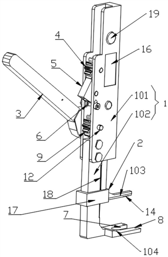
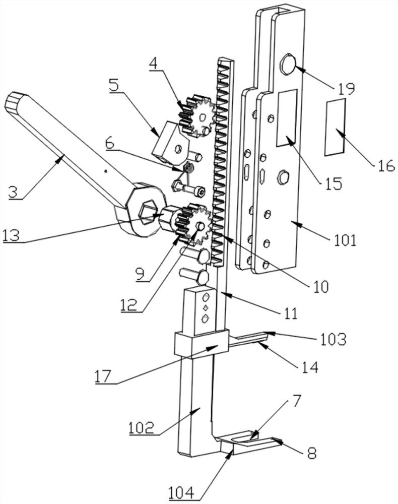
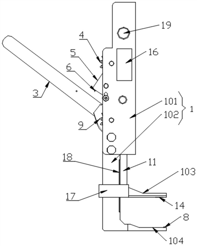
[0042] refer to Figure 1 to Figure 5, the present application discloses a clamp fastening device, including a bracket 1, the bracket 1 includes a housing 101 and a fixing pliers 102, the cross section of the housing 101 is a U-shaped structure, and the fixing pliers 102 are L-shaped structure, its top end is inserted into the housing 101, and is fixedly connected with the housing 101 by bolts, and its bottom is a lower chuck vertically connected to it;

[0043] The fastening device also includes a closing pliers 2, the two ends of the closing pliers 2 are respectively integrally connected with an upper chuck 103 and a connecting sleeve 17, the connecting sleeve 17 is a ring structure, and the sliding sleeve is placed on the fixed pliers 102, and The cross-section of the fixed clamp 102 is preferably square or rectangular, so as to avoid the rotation of the closed clamp 2, ensure that the upper clamp 103 and the lower clamp are always in a position facing each other, and impro...

Embodiment approach 2

[0054] refer to Figure 1 to Figure 5 , this embodiment is an optional embodiment of the present invention, which discloses a clamp fastening device on the basis of Embodiment 1, including a bracket 1, and the bracket 1 includes a fixedly connected housing 101 and a fixed clamp 102, the housing 101 has a U-shaped cross-section, and a PCB control board 15 is fixedly arranged in its side wall, and at the same time, a display screen 16 connected to the PCB control board 15 is also provided on the surface of the housing 101;

[0055] The fixed clamp 102 is also provided with a distance sensor 18 connected to the PCB control board 15. The distance sensor 18 is preferably a capacitive ranging sensor, which has small size, simple structure, high resolution and accuracy, fast measurement speed, and high performance. Low power consumption, low cost, and low requirements for the use environment; it is fixedly arranged on the back or side of the fixed pliers 102, and at the same time, wh...

Embodiment approach 3

[0061] refer to Image 6 , this embodiment is another optional embodiment of the present invention, which discloses a fastening method based on the clamp fastening device described in Embodiment 1, including the following steps:

[0062] S1. Place the open end of the clamp to be fastened directly under the closing pliers;

[0063] First lay the cable and the clamp to be installed, and then insert the end of the fastening device provided with the closing clamp and the fixed clamp into the installation station of the clamp to be installed, and at the same time snap into the bottom hole of the structure on the installation station In the installation groove, the connecting ear plate on the lower side of the opening end of the clamp to be installed is placed on the lower chuck, and it is limited by the limit bump; the upper chuck is snapped into the upper connecting ear plate The connection with the clamp body to be installed, so as to realize the connection between the clamp to ...


PUM


Abstract

The present invention discloses a hoop fastening device and method. The hoop fastening device comprises a support, a closing clamp is arranged on the support in a sliding manner, and meanwhile, a linear driving device is further arranged on the support. A power rod is hinged to the input end of the linear driving device, and the output end of the linear driving device makes contact with the closing clamp, so that the closing clamp is pushed to slide to press the opening end of a hoop to be mounted to be closed. During use, the support extends into the mounting space, the linear driving module is driven by rotating the power rod, and the linear driving module pushes the closing clamp to move downwards to press the hoop, so that the hoop is closed; after the hoop is completely closed, the linear driving mechanism is locked through a self-locking mechanism, so that the hoop to be mounted is always in a stable closed state. Compared with the prior art, the vertical size of a device is increased by changing the movement modes of the closing clamps at the same time, so that the mounting requirement of a narrow space is met; meanwhile, the advantages that the labor is saved, the operation can be conducted by one person and the like are achieved, and the mounting efficiency of the hoop is improved.

Description

technical field [0001] The present application relates to the technical field of assembly tool equipment, in particular to a clip fastening device and a fastening method. Background technique [0002] With the development of science and technology, airplanes have almost become an indispensable means of transportation. There are many control centers on the aircraft and the devices to be controlled by the control centers need to be connected by cables. For example, the control center of an aircraft can lead out a cable harness, and the cable harness is connected to equipment such as lighting or antennas, so that the control center can be connected to equipment such as lighting or antennas through the cable harness. [0003] In order to improve the economy of the aircraft, the reserved space for cable installation is small. During the cable laying process, the cables are generally bundled for easy management. The bundling and fixing of large aviation cables is a cumbersome and...

Claims


Application Information

Patent Timeline
Patent Type & Authority Applications(China)
IPC IPC(8): B25B27/00
CPCB25B27/00
Inventor 刘玉松蒋昊曹虎都刚宋修科徐扉飞王丹阳何磊黄毅光李明明夏清鹰张凯旋姚一军
Owner CHENGDU AIRCRAFT INDUSTRY GROUP
Why Eureka
Try Eureka