
Display screen, terminal and display screen making method

A production method and a technology of a display screen, which are applied in the field of display screens, can solve problems such as lack of integration, inconsistency, and influence on the visual effect of the display panel, and achieve the effect of enhancing the visual effect

Active Publication Date: 2016-10-19
ANHUI JINGZHUO OPTICAL DISPLAY TECH CO LTD
View PDF6 Cites 6 Cited by
  • Summary
  • Abstract
  • Description
  • Claims
  • Application Information

AI Technical Summary

Problems solved by technology

[0002] At present, most display screens are in order from outside to inside: transparent protection, optical glue, touch layer and display layer. This layered structure and the differences in applied materials will increase the reflection intensity of the visible area of ​​​​the panel and produce color cast. , for most black display panels, there is usually an ink area around the visible area, and there is an obvious difference in the reflection intensity between the visible area and the ink area. Usually, the reflection intensity of the visible area is larger than that of the ink area, and its The visual effect is much brighter than the ink area. In the off-screen state, the ink area and the visible area will be inconsistent, which will not achieve a seamless effect, which will affect the visual effect of the display panel.

Method used


Image

  • Display screen, terminal and display screen making method
  • Display screen, terminal and display screen making method
  • Display screen, terminal and display screen making method

Examples


Embodiment Construction

[0037] The following will clearly and completely describe the technical solutions in the embodiments of the present invention with reference to the drawings in the embodiments of the present invention.

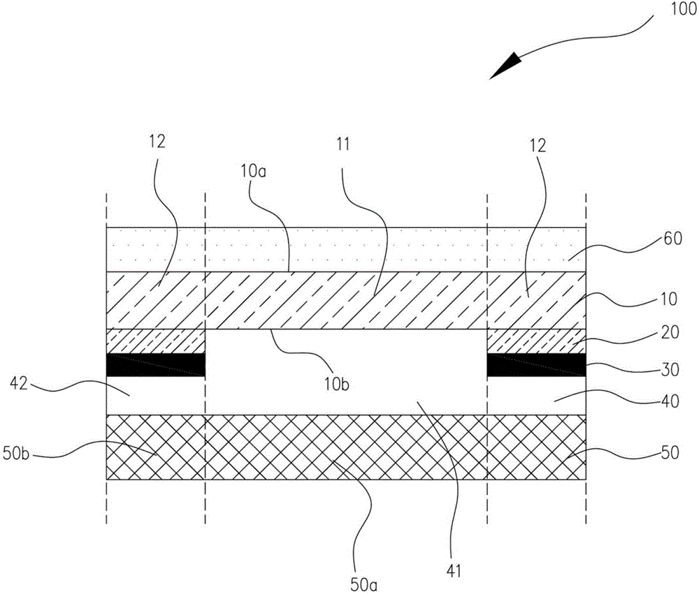
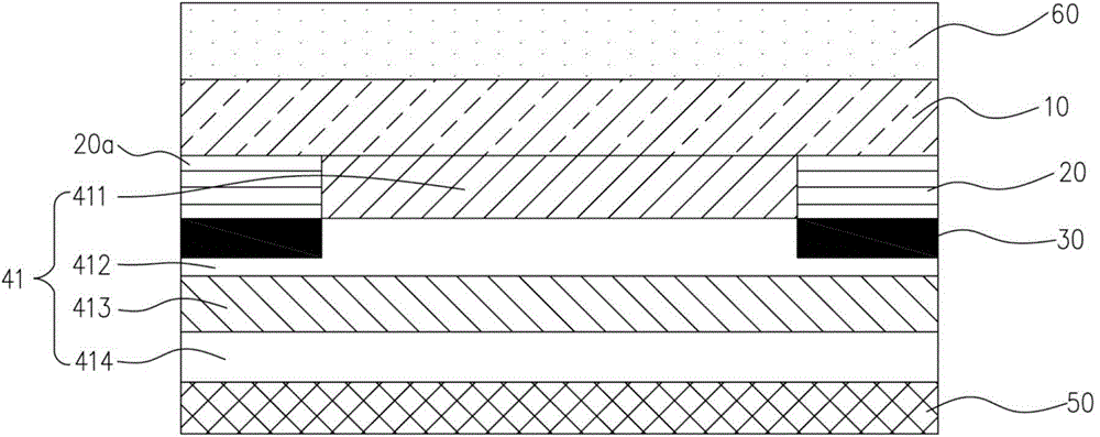
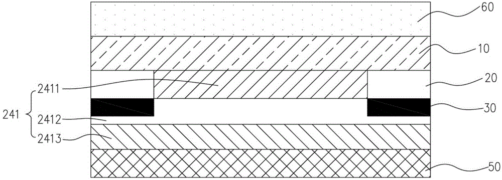
[0038] see figure 1 and figure 2 , a display screen 100 provided by the present invention, the display screen 100 includes a transparent protective plate 10, a reflective film 20, an ink layer 30, a functional layer 40 and a display layer 50 stacked in sequence, and the transparent protective plate 10 has a visible window 11 and a non-visible window 12, the non-visible window 12 surrounds the visible window 11, the reflective film 20 and the ink layer 30 are sequentially covered on the non-visible window 12, the functional layer 40 and the The display layer 50 sequentially covers the non-visible window 12 and the visible window 11 . The functional layer 40 can be an optical glue, used to attach the display layer 50 to the transparent protective plate 10; it can also be a to...


PUM

PropertyMeasurementUnit
Thicknessaaaaaaaaaa

Abstract

The invention discloses a display screen, a terminal and a display screen making method; the display screen comprises a display layer, a function layer, an ink layer, a reflective film and a transparent protection plate; the display layer comprises a visible zone and a non-visible zone surrounding the visible zone; the function layer is provided with a visible function layer corresponding to the visible zone, and provided with a non-visible function layer corresponding to the non-visible zone; the ink layer is stacked on the non-function layer corresponding to the non-visible zone; the reflective film is stacked on the ink layer corresponding to the non-visible zone; the refractive index of the reflective film is same with that of the visible function layer; the transparent protection plate comprises a visible window corresponding to the visible zone, and a non-visible window corresponding to the non-visible zone; the reflective film can increase the reflection intensity of the ink layer, thus allowing the reflection intensity of the ink layer and the display layer in the visible zone becomes consistent.

Description

technical field [0001] The invention relates to the field of display screens, in particular to a display screen, a terminal and a method for manufacturing a display screen. Background technique [0002] At present, most display screens are in order from outside to inside: transparent protection, optical glue, touch layer and display layer. This layered structure and the differences in applied materials will increase the reflection intensity of the visible area of ​​​​the panel and produce color cast. , for most black display panels, there is usually an ink area around the visible area, and there is an obvious difference in the reflection intensity between the visible area and the ink area. Usually, the reflection intensity of the visible area is larger than that of the ink area, and its The visual effect is much brighter than the ink area. In the off-screen state, the ink area and the visible area will be inconsistent, and the seamless effect will not be achieved, which will...

Claims


Application Information

Patent Timeline
IPC IPC(8): G06F3/041
Inventor 许鹏程芸唐彬
Owner ANHUI JINGZHUO OPTICAL DISPLAY TECH CO LTD
Learn More