Method and device for projecting a panoramic image with a variable resolution

a technology of variable resolution and projection method, applied in the direction of projectors, panoramic photography, instruments, etc., can solve the problem that the observer cannot see all the pixels of the projected image with the same angular resolution, and achieve the effect of constant angular resolution

Active Publication Date: 2011-09-13
IMMERVISION INC
View PDF19 Cites 60 Cited by
  • Summary
  • Abstract
  • Description
  • Claims
  • Application Information

AI Technical Summary

Benefits of technology

[0008]It is therefore proposed to provide an improved projection of panoramic images, so that the observer sees all the points of the projected image with a constant angular resolution.
[0010]More globally, it is wished to improve the visual perception of the panoramic images projected by a panoramic projection system.

Problems solved by technology

The result is that an observer cannot see all the pixels of the projected image with the same angular resolution.

Method used


Image

  • Method and device for projecting a panoramic image with a variable resolution
  • Method and device for projecting a panoramic image with a variable resolution
  • Method and device for projecting a panoramic image with a variable resolution

Examples


Embodiment Construction

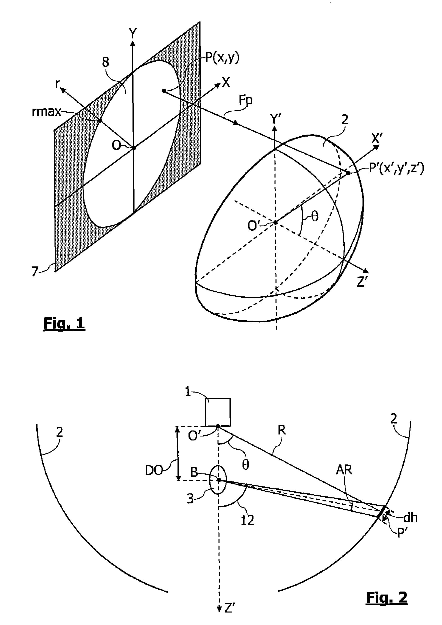
[0038]A first embodiment of a panoramic projection system is shown by FIG. 2. Very schematically, the system is configured to project on a projection surface 2 a plane panoramic image. The projection system comprises an optical device for projecting panoramic images 1, and a screen of substantially hemispherical shape 2, which center of curvature O′ is located on the optical axis O′Z′ of the projection optical device 1. An observer 3 is located at an observation point B on the optical axis O′Z′, between the device 1 and the projection surface 2. The projection optical device 1 comprises an active matrix for image generation, for example of the type DMD (Digital Micromirror Device), LCD (Liquid Crystal Display), LCOS (Liquid Crystal On Silicon), GLV (Grating Light Valves), MEMS (Micromechanical System).

[0039]According to one embodiment, the optical device 1 is configured to project an image having an optimized resolution in which the points projected on the projection surface have a ...


PUM


Abstract

Embodiments include a method and apparatus for projecting a panoramic image, the method including steps of generating an image on an image generation surface, and then projecting the generated image on a projection surface to obtain a panoramic projected image, the points of the generated image being projected on the projection surface according to a non uniform distribution determined as a function of at least one parameter of a set comprising the shape of the generated image, the shape of the projection surface, and the position of an observation point of the projected image, in relation to the projection surface.

Description

TECHNICAL FIELD[0001]The present invention relates to the projection of panoramic images. The present invention more particularly relates to the projection of panoramic images covering a sphere portion of at least 360°×140° using a single image projection optical device.BACKGROUND[0002]The systems of projection of panoramic images conventionally comprise a panoramic projection optical device comprising an image generation device, and a projection surface facing the optical device. The projection optical devices are generally designed to project on the projection surface a panoramic image generally having a field of view greater than 140°, while keeping a constant distribution of the pixels in the projected image. The projection optical devices consist for example of a digital projector comprising a plane active matrix for image generation.[0003]The panoramic images are generally obtained using a panoramic objective of fisheye type having an angle of aperture of about 180°. Such a le...

Claims


Application Information

Patent Timeline
Patent Type & Authority Patents(United States)
IPC IPC(8): G03B21/00G03B21/14
CPCG03B21/14G03B21/142G03B37/00
Inventor ARTONNE, JEAN-CLAUDETHIBAULT, SIMON
Owner IMMERVISION INC
Why Eureka
Try Eureka