Directional light-emitting device

A light-emitting device and orientation technology, which is applied to lighting devices, components of lighting devices, semiconductor devices of light-emitting elements, etc., can solve problems such as slow response speed

Active Publication Date: 2016-10-26
江苏特力威信息系统有限公司
View PDF5 Cites 2 Cited by
  • Summary
  • Abstract
  • Description
  • Claims
  • Application Information

AI Technical Summary

Problems solved by technology

[0002] Existing directional lighting devices generally use mechanical rotation and directional lighting, such as stage lighting, and its disadvantage is that the response speed is slow

Method used


Image

  • Directional light-emitting device
  • Directional light-emitting device
  • Directional light-emitting device

Examples


Embodiment Construction

[0020] The present invention will be further described below in conjunction with the accompanying drawings and embodiments.

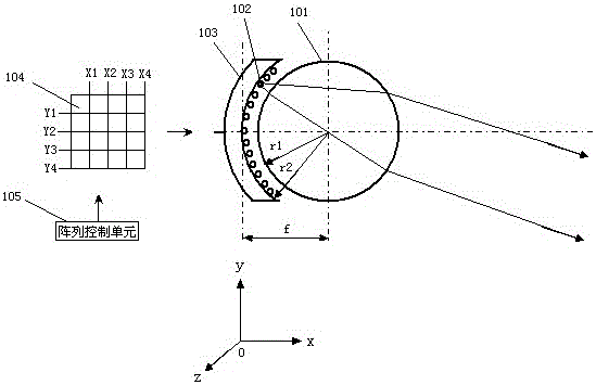
[0021] figure 1 It is the structure and schematic diagram of the directional light emitting device. The ball center of the spherical lens 101 and the hemispherical back cover 103 coincide, and the concave surface of the hemispherical back cover 103 is evenly arranged with a LED chip lattice, 102 is one of the LED chips, and the LED chip lattice is connected into an array circuit and is controlled by an array switch 104 For driving control, the array switch 104 is connected to the array control unit 105, and the array control unit is controlled by computer output.

[0022] The focal length of the spherical lens is f, and the radius of the concave surface of the hemispherical rear cover is r2, which satisfies r2=f, so that any LED chip on the LED chip lattice is at the focal length f of the spherical lens (that is, the focal plane of the spherical lens a...


PUM


Abstract

The invention relates to the field of LED light reflection, in particular to a directional light-emitting device. The directional light-emitting device is characterized by comprising a spherical lens and a hemispherical back cover, wherein an LED array is evenly arranged on the concave surface of the hemispherical back cover, the focal length of the spherical lens is f, the radius of the concave surface of the hemispherical back cover is r2, and r2 is equal to f. The radius of the spherical lens is r1, the refractive index of the spherical lens is n, and r2 is equal to nr1 / 2(n-1). The directional light-emitting device has the beneficial effect of being capable of achieving directional lighting at the microsecond level.

Description

technical field [0001] The invention relates to the field of LED light reflection, in particular to a directional light emitting device. Background technique [0002] Existing directional lighting devices generally adopt mechanical rotation and directional lighting, such as stage lighting, and their disadvantage is that the response speed is slow. Contents of the invention [0003] The purpose of the present invention is to provide a directional light-emitting device that can realize directional illumination at the microsecond level. [0004] The technical scheme adopted in the present invention is: [0005] A directional light-emitting device, characterized in that: the device includes a spherical lens, a hemispherical rear cover, the concave surface of the hemispherical rear cover is uniformly arranged with LED dot matrix, the focal length of the spherical lens is f, and the radius of the concave surface of the hemispherical rear cover is r2, Satisfy r2=f. [0006] ...

Claims


Application Information

Patent Timeline
Patent Type & Authority Applications(China)
IPC IPC(8): F21K9/68F21K9/69F21V5/04F21V7/04F21V23/04F21V14/00F21Y115/10
CPCF21V5/041F21V5/045F21V7/04F21V14/00F21V23/04
Inventor 浦跃东吴东辉
Owner 江苏特力威信息系统有限公司
Why Eureka
Try Eureka