Transmitter supervision method, device and system

A technology of transmitter and display mode, applied in transmitter monitoring, transmission system, digital transmission system, etc., can solve the problems of high work cost, large workload, easy error or omission of recorded information, etc., to improve supervision efficiency, The effect of reducing work costs

Pending Publication Date: 2016-11-02
SHIJIAZHUANG DEV ZONE TAISHUN ELECTRONICS COMM
View PDF3 Cites 0 Cited by
  • Summary
  • Abstract
  • Description
  • Claims
  • Application Information

AI Technical Summary

Problems solved by technology

[0003] Due to the large number of transmitters and frequent use, relying on manual records will bring a lot of workload, and the recorded information is prone to errors or omissions; errors or omissions in recorded information will lead to lack of supervision of transmitters, which is not conducive to Maintenance of transmitters and assessment and prediction of health status
[0004] Aiming at the problems of high work cost and poor reliability of the recorded data in the above-mentioned method of manually supervising the transmitter, no effective solution has been proposed yet

Method used


Image

  • Transmitter supervision method, device and system
  • Transmitter supervision method, device and system
  • Transmitter supervision method, device and system

Examples


Embodiment 1

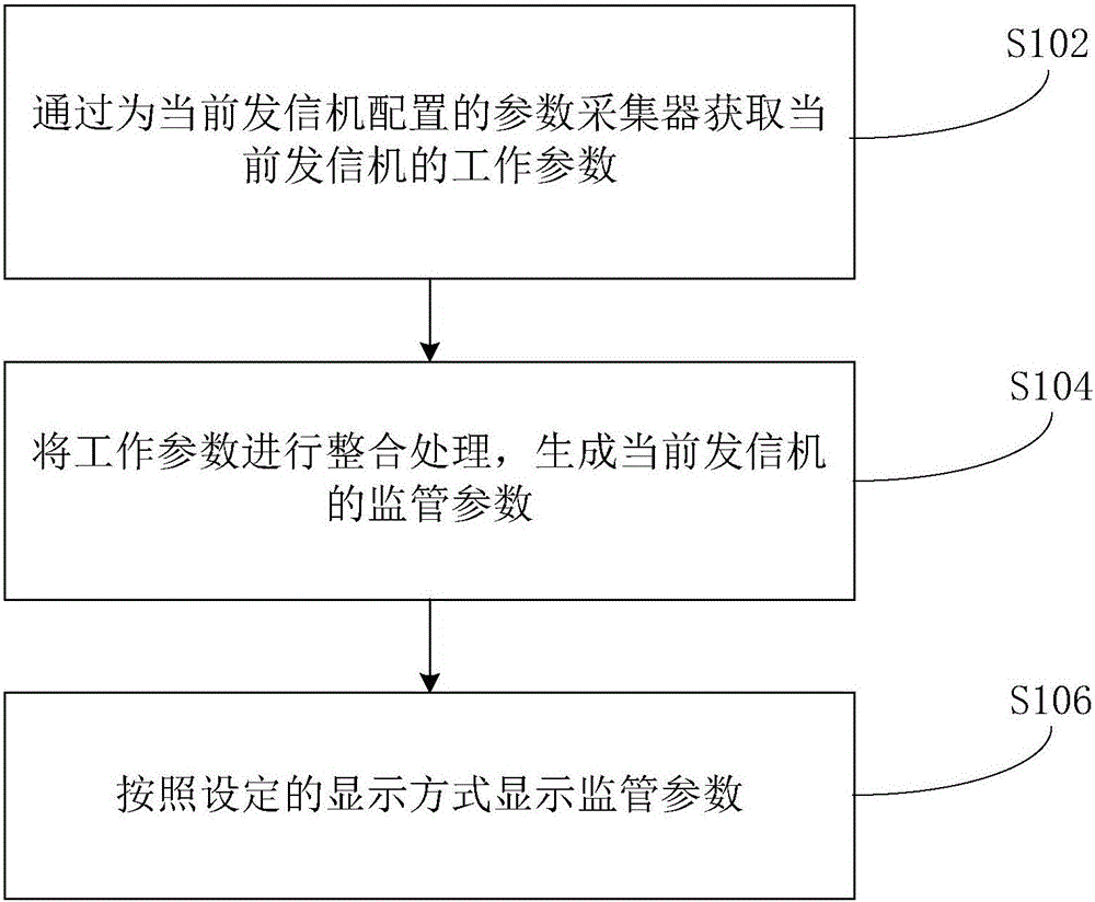
[0028] see figure 1 The flow chart of a method for monitoring a transmitter is shown, including the following steps:

[0029] Step S102, obtaining the working parameters of the current transmitter through a parameter collector configured for the current transmitter;

[0030] Step S104, integrating the working parameters to generate supervisory parameters of the current transmitter;

[0031] Step S106, displaying the supervision parameters according to the set display mode.

[0032] In the above method of this embodiment, relatively accurate and complete working parameters of the transmitter can be automatically obtained through the parameter collector; by integrating and processing the above working parameters, supervision parameters are generated, and the supervision parameters can more reliably reflect the transmitter and by displaying the supervision parameters according to the set display mode, the automatic supervision of the transmitter can be realized; the above metho...

Embodiment 2

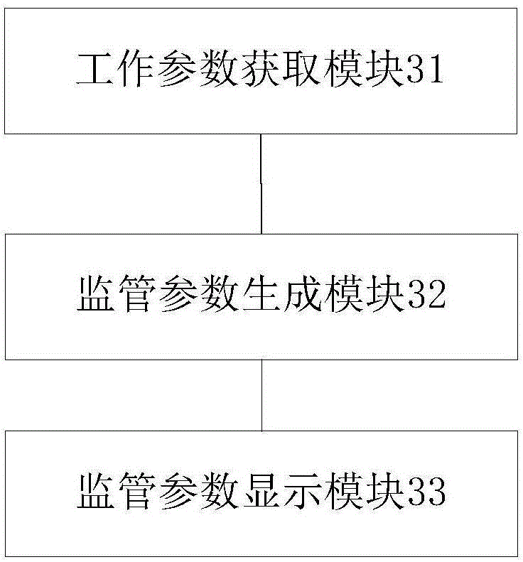
[0055] Corresponding to the above method, this embodiment also provides a transmitter monitoring device, see image 3 A schematic structural diagram of a transmitter supervisory device shown, including the following modules:

[0056] The working parameter obtaining module 31 is used for obtaining the working parameters of the current transmitter through the parameter collector configured for the current transmitter;

[0057] The supervisory parameter generation module 32 is used to integrate the working parameters to generate supervisory parameters of the current transmitter;

[0058] The supervision parameter display module 33 is used to display the supervision parameters according to the set display mode.

[0059] In the above device of this embodiment, relatively accurate and complete working parameters of the transmitter can be automatically obtained through the parameter collector; by integrating and processing the above working parameters, a supervision parameter is gen...

Embodiment 3

[0080] see Figure 5 Shown is a schematic diagram of the structure of a transmitter supervision system.

[0081]The transmitter monitoring system includes a transmitter monitoring device 50 and a parameter collector 51 connected to the transmitter monitoring device 50 . The transmitter supervising apparatus 50 may be implemented by using the structure of the transmitter supervising apparatus provided in the above-mentioned Embodiment 2, which will not be repeated here.

[0082] The above-mentioned parameter collector 51 collects the working parameters of the transmitter, and sends the working parameters to the above-mentioned transmitter monitoring device 50; the above-mentioned transmitter monitoring device 50 integrates the working parameters to generate the monitoring parameters of the current transmitter, The supervisory parameters are displayed according to a set display mode, and the set display mode includes at least one of the following graphic display modes, table di...


PUM


Abstract

The invention provides a transmitter supervision method, device and system. The method comprises the steps that the working parameters of a current transmitter are acquired by a parameter acquisition device configured for the current transmitter; the working parameters are integrated so that the supervision parameters of the current transmitter are generated; and the supervision parameters are displayed according to a preset display mode. With application of the transmitter supervision method, device and system, the efficiency of transmitter supervision can be enhanced.

Description

technical field [0001] The present invention relates to the technical field of transmitters and transmitter supervision, and in particular, to a transmitter supervision method, device and system. Background technique [0002] A transmitter is a device used to transmit short-wave radio signals by means of an antenna feeder system. At present, the use, detection, management and maintenance of the transmitter mostly rely on the manual operation of the operator, and the operator records the operation status of the transmitter on a paper carrier or input it into a computer storage medium. [0003] Due to the large number of transmitters and frequent use, relying on manual recording will bring a lot of work, and the recorded information is prone to errors or omissions; errors or omissions of recorded information will lead to the lack of supervision of transmitters, which is not conducive to the Maintenance of transmitters and assessment and prediction of state of health. [0004...

Claims


Application Information

Patent Timeline
Patent Type & Authority Applications(China)
IPC IPC(8): H04L29/08H04L12/24H04B17/10H04B17/20
CPCH04B17/10H04B17/20H04L41/06H04L67/025
Inventor 周希国周贤博苏鸿宾朱建明郝向阳
Owner SHIJIAZHUANG DEV ZONE TAISHUN ELECTRONICS COMM
Why Eureka
Try Eureka