Intravenous needle tab feeding mechanism

A technology of venous needles and fins, which is applied in the direction of conveyor objects, transportation and packaging, slideways, etc., and can solve the problems of inconsistent positions of plastic needle exhaust ports and low assembly efficiency

Active Publication Date: 2016-11-09
梁启明
View PDF16 Cites 11 Cited by
  • Summary
  • Abstract
  • Description
  • Claims
  • Application Information

AI Technical Summary

Problems solved by technology

However, the position of the exhaust port of the plastic needle cannot be unified, which re

Method used


Image

  • Intravenous needle tab feeding mechanism
  • Intravenous needle tab feeding mechanism
  • Intravenous needle tab feeding mechanism

Examples


Embodiment 1

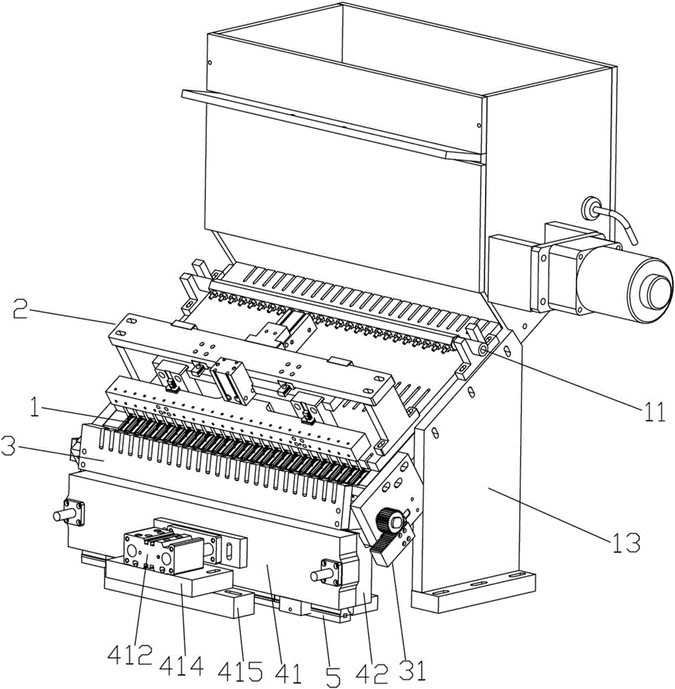
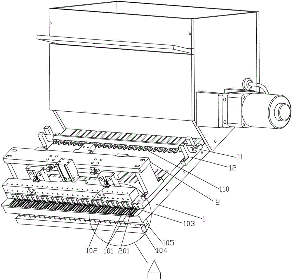
[0055]Such as Figure 2~18 As shown, the present invention provides a specific embodiment of a venous needle flap feeding mechanism, including a needle handle main board 1 for conveying the venous needle flap 6, a pusher assembly 2 for pushing the venous needle flap 6, and a The feeding seat 3 that rotates and guides the delivery of the venous needle wing 6, the guide device for conveying the venous needle wing 6 downward, and the venous needle jig 5 that is used to receive the venous needle delivery in the guide device; the pusher assembly 2. It is possible to push the vein needle fin 6 conveyed along the needle handle main board 1 to the bottom end of the needle handle main board 1 into the feeding seat 3, and then pass the vein needle fin 6 in the feeding seat 3 through the guide device Delivered downwards in the venous needle fixture 5.

[0056] Such as figure 2 , image 3 with Image 6 As shown, the needle handle main board 1 is provided with a plurality of grooves I...

Embodiment 2

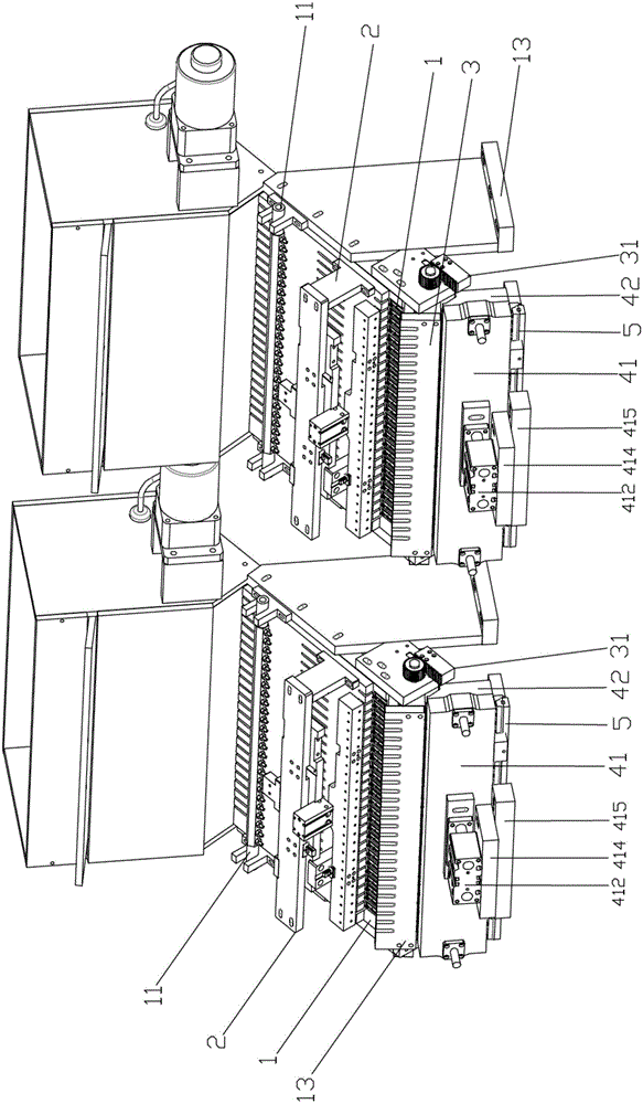
[0073] On the basis of above-mentioned embodiment 1, as figure 1 As shown, two venous needle fin feeding mechanisms in the present invention are arranged side by side, wherein several venous needle jigs 5 can be discharged along multiple falling tracks of the bottom guide devices of the two venous needle fin feeding mechanisms. The arrangement direction moves circularly or reciprocally; since the length of the overlapping part between two adjacent slotted holes 502 in the groove V501 provided on the venous needle jig 5 is half the length of the slotted hole 502 or half The width of a venous needle wing 6, so a venous needle fixture 5 (that is, a unit length) embedded slot 502 can accommodate two rows of venous needle wings 6 conveyed by the venous needle wing feeding mechanism, thereby realizing A venous needle jig 5 can sequentially receive a row of the two venous needle fin feeding mechanisms respectively transported by moving in the arrangement direction of a plurality of f...


PUM


Abstract

The invention provides an intravenous needle tab feeding mechanism, comprising a shank main plate for conveying intravenous needle tabs, a push assembly for pushing intravenous needle tabs, a feeding base for rotationally guiding intravenous needle tabs, a guide device for conveying intravenous needle tabs downwardly, and an intravenous needle jig for receiving intravenous needle tabs conveyed down from the guide device; the push assembly can convey the intravenous needle tabs into the feeding base that are conveyed from the shank main plate to the bottom end of the shank main plate, and the intravenous needle tabs in the feeding base are conveyed down into the intravenous needle jig through the guide device. It can be effectively guaranteed that intravenous needle tabs are conveyed neatly, precisely and efficiently; the shank main plate and a groove I thereof are inclined, the feed base can provide rotational guide control, and therefore, a travel distance for conveying intravenous needle tabs is effectively shortened and whole space required by the intravenous needle tab feeding mechanism is effectively reduced.

Description

technical field [0001] The invention relates to the technical field of venous needle wing assembly equipment among medical devices, in particular to a venous needle wing feeding mechanism. Background technique [0002] With the improvement of social living standards, infusion as an important treatment method is more widely used in clinical cases. Infusion is a large dose of injection (more than 100ml administered at one time) injected into the body by intravenous infusion. During the infusion, the drip rate of the injection is adjusted through the infusion set, and it enters the vein continuously and stably to replenish body fluids, electrolytes or provide nutrients. . [0003] In the medical infusion industry, disposable infusion sets have been widely used due to their convenience, safety and hygiene. Disinfection is not required during infusion, and the user only needs to unpack the package and connect the infusion set and the venous needle together. However, unclean in...

Claims


Application Information

Patent Timeline
IPC IPC(8): B65G11/02B65G11/20B65G47/82B65G47/24
CPCB65G11/023B65G11/203B65G47/24B65G47/82
Inventor 梁启明
Owner 梁启明
Why Eureka
Try Eureka