
Installation method of steel structure well frame components

An installation method and steel structure technology, applied in earthwork drilling, supporting devices, drilling equipment, etc., can solve the problems that conventional machinery cannot be installed, and structural parts cannot be installed in place according to the design, so as to achieve the effect of shortening the construction period

Active Publication Date: 2018-10-19
MECHANICAL & ELECTRICAL INSTALLATION ENG CO LTD OF CHINA COAL NO 3 CONSTR GRP CORP LTD +1
View PDF4 Cites 0 Cited by
  • Summary
  • Abstract
  • Description
  • Claims
  • Application Information

AI Technical Summary

Problems solved by technology

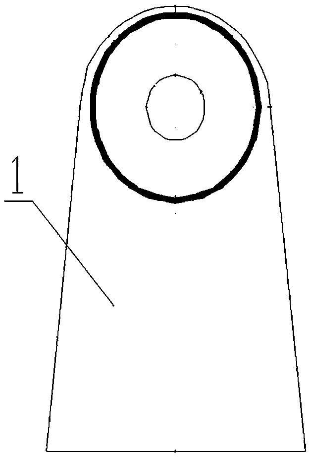
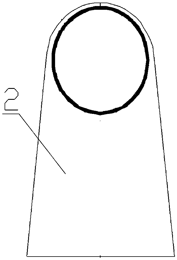
[0004] The purpose of the present invention is to provide a method for installing steel structure derrick components to solve the technical problem that the local components of the derrick, large platforms and other structural parts cannot be installed in place according to the design, or cannot be installed with conventional machinery

Method used


Image

  • Installation method of steel structure well frame components
  • Installation method of steel structure well frame components
  • Installation method of steel structure well frame components

Examples


Embodiment Construction

[0056] Hereinafter, an embodiment of a method of installing a steel structure derrick member of the present invention will be described with reference to the accompanying drawings.

[0057] The examples described here are specific specific implementations of the present invention, and are used to illustrate the concept of the present invention. They are all explanatory and exemplary, and should not be construed as limiting the implementation of the present invention and the scope of the present invention. In addition to the embodiments described here, those skilled in the art can also adopt other obvious technical solutions based on the claims of the application and the contents disclosed in the description, and these technical solutions include adopting any obvious changes made to the embodiments described here. Replacement and modified technical solutions.

[0058] The accompanying drawings in this specification are schematic diagrams, which assist in explaining the concept ...


PUM


Abstract

The invention discloses an installation method for a steel-structure derrick member. The installation method for the steel-structure derrick member comprises the step 1 that a fixed hinge is installed and fixed on a derrick inclined frame; the step 2 that a movable hinge is installed and fixed to a member to be fixed to a derrick; the step 3 that the member is hoisted to enable the movable hinge fixedly connected with the member to be close to the fixed hinge, and then a pin shaft is inserted into the fixed hinge and the movable hinge; the step 4 that the member is turned over with the pin shaft as the center to reach the preset installation position of the inclined frame; the step 5 that the member and the derrick inclined frame are aligned according to the design requirements, and after alignment, all joints of the combination surface of the member and the derrick inclined frame are fixed through spot welding; and the step 6 that all the joints of the combination surface of the member and the derrick inclined frame are connected through full-length welding. By means of the installation method for the steel-structure derrick member, the technical problem that a local member, a large platform and other structural parts of the derrick can not be installed in place according to the design, or installation can not be completed through a common machine is solved, the construction task can be completed safely and efficiently, and the construction period of the whole project can be greatly shortened.

Description

technical field [0001] The invention belongs to the technical field of derrick installation and construction, and in particular relates to a method for installing steel structure derrick components. Background technique [0002] In the process of mine construction, due to the constraints of the structural characteristics of the steel structure derrick itself, it is often affected by factors such as process arrangements and site conditions during construction, resulting in partial components of the derrick, large platforms and other structural parts that cannot be installed in place according to the design, or Installation cannot be accomplished with conventional machinery. [0003] The various influencing factors are as follows: First, due to the small space of the construction site, the operating height (either too low or too high) and the safety risk factor, it is difficult to use only common tools such as chain hoists and jacks. Truck cranes cannot successfully complete ...

Claims


Application Information

Patent Timeline
Patent Type & Authority Patents(China)
IPC IPC(8): E21B15/00
CPCE21B15/00
Inventor 王传勇程为书韩友明吴向东张鲁鲁
Owner MECHANICAL & ELECTRICAL INSTALLATION ENG CO LTD OF CHINA COAL NO 3 CONSTR GRP CORP LTD
Learn More