Tractor, pipe tool drift diameter device and method

A tractor and diameter technology, used in earth-moving drilling, wellbore/well components, etc., can solve the problems of operator's hand injury, lack of passing tools, low efficiency, etc.

Inactive Publication Date: 2020-07-17
BC P INC CHINA NAT PETROLEUM CORP +1
View PDF12 Cites 0 Cited by
  • Summary
  • Abstract
  • Description
  • Claims
  • Application Information

AI Technical Summary

Problems solved by technology

However, the current drilling site still stays at the method of completely manually pulling through the gauge for drilling tools and various casings during the construction operation, and there is no special passing tool.
The menstrual passage method in the prior art is not only inefficient, but also has great potential safety hazards, and it is easy to hurt the hands of the operator

Method used


Image

  • Tractor, pipe tool drift diameter device and method
  • Tractor, pipe tool drift diameter device and method
  • Tractor, pipe tool drift diameter device and method

Examples


Embodiment 1

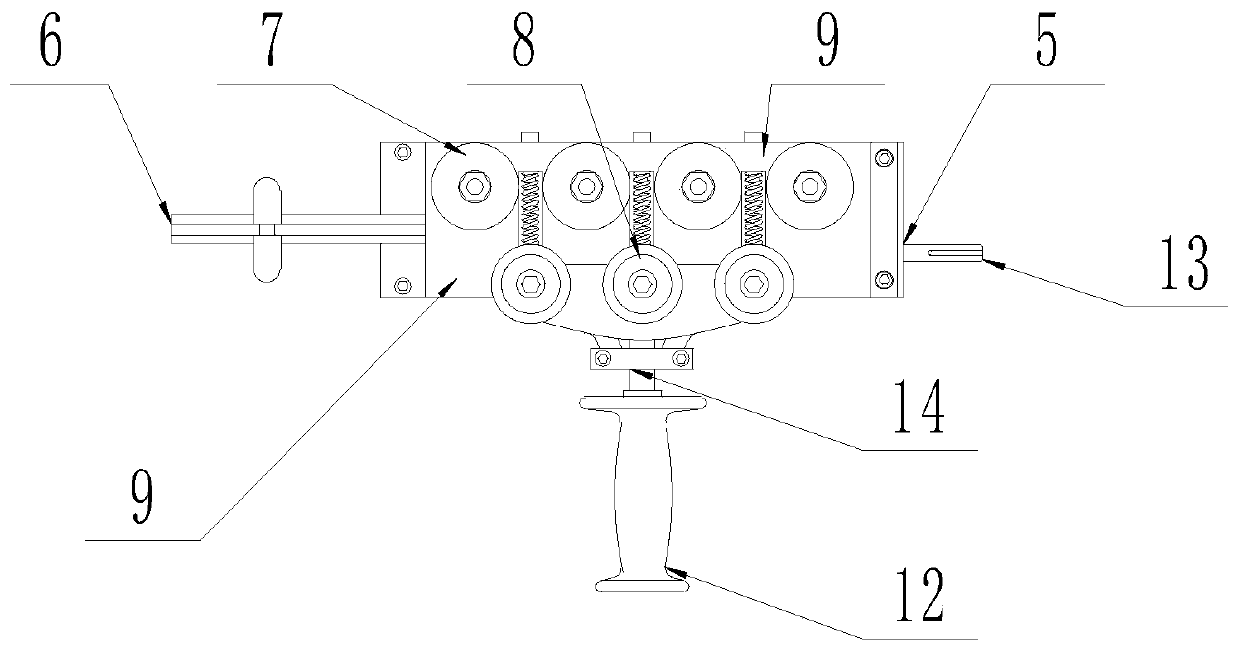
[0038] according to Figure 1-6 A retractor shown, including

[0039] Guide rope holder 10,

[0040] The moving guide rope rotating mechanism, the moving guiding rope rotating mechanism is connected in the guide rope fixing seat 10, the output end and the input end of the moving guiding rope rotating mechanism all extend to the outside of the guiding rope fixing seat 10;

[0041] Moving rope wheel 7, moving rope wheel 7 is arranged on the outside of fixed seat 10 and is connected with the output end of moving rope rotating mechanism;

[0042] A sliding part, the sliding part is connected on the guide rope fixing seat 10;

[0043] The static guide sheave group 8, the static guide sheave group 8 is connected with the sliding part, the static guide sheave group 8 and the dynamic guide sheave 7 are arranged alternately and are located on the same plane.

[0044] In actual use, firstly, the wire rope head is inserted into the tractor 4, so that the steel wire rope passes between...

Embodiment 2

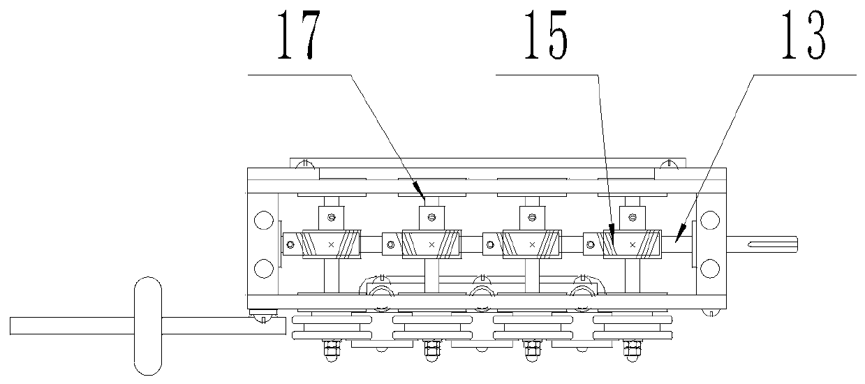
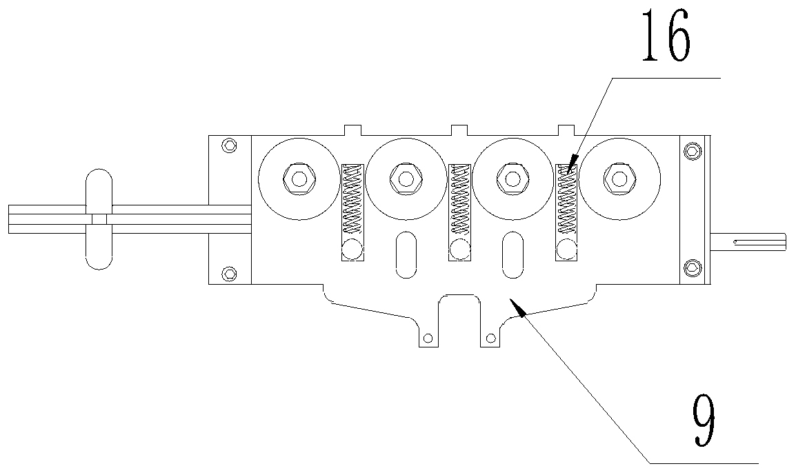
[0049] according to Figure 1-4 The retractor shown is different from the first embodiment in that: the guide wire fixing seat 10 is a rectangular frame structure with an open surface, and a first through hole is opened in the center of a side of the rectangular frame along the width direction 5. At least one pair of second through holes 11 are evenly and symmetrically opened on two opposite sides of the rectangular frame along the length direction; the moving guide rope rotation mechanism includes a moving connecting shaft 13, a driving gear 15 and a driven wheel shaft 17. The two ends of the connecting shaft 13 are respectively connected to the two sides of the guide rope fixing seat 10 along the width direction in rotation, and one end of the connecting shaft 13 extends to the outside of the guide rope fixing seat 10 through the first through hole 5, and is connected On the shaft 13, lead screws are arranged at equal intervals; the driven wheel shaft 17 is rotatably connect...

Embodiment 3

[0054] according to figure 2 and Figure 4 The shown tractor differs from the first embodiment in that: four pairs of second through holes 11 are provided, and the number of the second through holes 11 matches the number of 15 lead screws and driving gears.

[0055] In actual use, the number of setting of the leading screw and driving gear 15 can be determined according to the actual situation of the operation, and when the force of traction is large, the setting number of the leading screw and driving gear 15 is relatively large.


PUM


Abstract

The invention belongs to the technical field of petroleum drilling equipment, and particularly relates to a tractor, and a pipe tool drift diameter device and method. The drift diameter device is composed of a steel wire rope, a support, the tractor, a rope disc, a drift diameter gauge hanging ring and a driving mechanism, wherein the tractor and the rope disc are fixedly connected to the support,the steel wire rope is wound around the rope disc, one end of the steel wire rope penetrates through the tractor to be connected with the drift diameter gauge hanging ring, and the tractor is drivenby the driving mechanism to complete penetration and stretching of the steel wire rope. The drift diameter device is adopted for drift diameter of a pipe tool, and is efficient and safe.

Description

technical field [0001] The invention belongs to the technical field of petroleum drilling equipment, and in particular relates to a tractor, a pipe diameter device and a method. Background technique [0002] With the increasing emphasis on safety work at the drilling site, the pursuit of intrinsic safety of equipment has become a consensus. But the current drilling site still stays in the method of completely manually pulling the through-gauge for drilling tools and various casing pipes in the construction operation process, and there is no special-purpose through-through tool. The menstruation-passing method in the prior art is not only inefficient, but also has great potential safety hazards, and the hand of the operator is easily injured. Contents of the invention [0003] The invention provides a retractor, a pipe diameter device and a method, and aims to provide a pipe diameter device with high efficiency and high safety. [0004] In order to achieve the above objec...

Claims


Application Information

Patent Timeline
Patent Type & Authority Applications(China)
IPC IPC(8): E21B29/10
CPCE21B29/10
Inventor 鲁卫华贺会锋赵廷龙崔宇史配铭杨光王俊海程华林刘晓燕
Owner BC P INC CHINA NAT PETROLEUM CORP
Why Eureka
Try Eureka