Hot riveting structure

A technology of hot riveting and riveting head, applied in the direction of binding, etc., can solve the problems of cumbersome transmission process, low working efficiency of hot riveting structure, complicated lifting structure of hot riveting structure, etc., and achieve the effect of high hot riveting efficiency

Inactive Publication Date: 2016-11-16
ZHEJIANG ZHIYUAN OFFICE EQUIP MFG
View PDF8 Cites 0 Cited by
  • Summary
  • Abstract
  • Description
  • Claims
  • Application Information

AI Technical Summary

Problems solved by technology

[0002] Binding machines generally use hot riveting to bind documents. Compared with other methods, hot riveting is faster and has better adaptability to paper thickness. However, there are several hot riveting structures in existing hot riveting binding machines. Disadvantages, the first existing hot riveting structure usually needs to share a motor with the drilling structure, which makes the working efficiency of the hot riveting structure very low, and the hot riveting can only be carried out after the drilling is completed; the second existing hot riveting The design of the lifting structure of the riveting structure is too complicated, and the transmission process is also very cumbersome, which increases the probability of damage to the hot riveting structure

Method used


Image

  • Hot riveting structure

Examples


Embodiment Construction

[0017] The present invention will be described in further detail below in conjunction with the accompanying drawings.

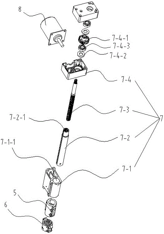
[0018] like figure 1 As shown, the embodiment of the present invention includes an upper rivet head 5, a lower rivet head 6, a telescopic device 7 and a transmission motor 8, and is characterized in that: the upper rivet head 5 is connected with the telescopic device 7, and moves linearly up and down relative to the lower rivet head 6, The transmission motor 8 is connected with the expansion device 7; the expansion device 7 includes a hot riveting seat 7-1, a hot riveting shaft 7-2, a hot riveting screw rod 7-3, a transmission box 7-4, and a hot riveting seat 7-1. The position of the head 6 is fixed, the hot riveting seat 7-1 is socketed with the hot riveting shaft 7-2, the hot riveting shaft 7-2 is screwed with the hot riveting screw rod 7-3, and the hot riveting screw rod 7-3 is connected with the transmission box 7 -4 output connection.

[0019] like fi...


PUM


Abstract

The invention discloses a hot riveting structure. The hot riveting structure comprises an upper riveting head, a lower riveting head, a telescopic device and a transmission motor. The upper riveting head is connected with the telescopic device, and does linear lifting motion relative to the lower riveting head; the transmission motor is connected with the telescopic device, and the telescopic device comprises a hot riveting base, a hot riveting shaft, a hot riveting lead screw and a transmission box, the position, relative to the lower riveting head, of the hot riveting base is fixed, the hot riveting base and the hot riveting shaft are sleeved, the hot riveting shaft is in screw joint with the hot riveting lead screw, and the hot riveting lead screw is connected with the output end of the transmission box. The hot riveting structure has the beneficial effect of being high in hot riveting efficiency.

Description

technical field [0001] The invention relates to the field of office equipment, in particular to a heat riveting structure. Background technique [0002] Binding machines generally use hot riveting to bind documents. Compared with other methods, hot riveting is faster and has better adaptability to paper thickness. However, there are several hot riveting structures in existing hot riveting binding machines. Disadvantages, the first existing hot riveting structure usually needs to share a motor with the drilling structure, which makes the working efficiency of the hot riveting structure very low, and the hot riveting can only be carried out after the drilling is completed; the second existing hot riveting The design of the lifting structure of the riveting structure is too complicated, and the transmission process is also very cumbersome, which increases the probability of damage to the hot riveting structure. Contents of the invention [0003] Aiming at the deficiencies of...

Claims


Application Information

Patent Timeline
Patent Type & Authority Applications(China)
IPC IPC(8): B42B5/02
CPCB42B5/02
Inventor 阮永华谭显斌蒋恩德
Owner ZHEJIANG ZHIYUAN OFFICE EQUIP MFG
Why Eureka
Try Eureka