Voltage calibration circuit and its programming equipment

A voltage calibration and circuit technology, which is applied in the direction of adjusting electrical variables, instruments, control/regulation systems, etc., can solve the problems of large wiring impedance, reduced reliability of the burning process, and complex adapter boards, etc., to achieve simple circuit structure, The effect of improving output yield and ensuring reliability

Active Publication Date: 2017-11-03
KUNSHAN GO VISIONOX OPTO ELECTRONICS CO LTD
View PDF5 Cites 0 Cited by
  • Summary
  • Abstract
  • Description
  • Claims
  • Application Information

AI Technical Summary

Problems solved by technology

[0003] However, in the process of programming parameters such as the voltage of the display panel by the above-mentioned programming device, since the programming device usually needs to support multiple different types of display panels to work at the same time, the adapter boards 6 and 8 are relatively complicated, and the programming device and The display panels need to be connected by adapter boards, adapter cables, etc., resulting in multiple transfers of the programming voltage and other signals through the wiring. Because the wiring path is too long and the wiring impedance is too large, the input to the display panel There is a large deviation between the final programming voltage and the preset voltage value, and the color coordinates and brightness of the display panel after programming will deviate greatly from the preset specification value, resulting in a decrease in the reliability of the programming process, and even As a result, the display panel cannot be used normally and cannot meet user needs

Method used


Image

  • Voltage calibration circuit and its programming equipment
  • Voltage calibration circuit and its programming equipment
  • Voltage calibration circuit and its programming equipment

Examples


Embodiment Construction

[0025] In order to further explain the technical means and effects of the present invention to achieve the intended purpose of the invention, the specific implementation, structure, Features and functions are described in detail below.

[0026] The aforementioned and other technical contents, features and effects of the present invention will be clearly presented in the following detailed description of the preferred embodiments with reference to the drawings. Through the description of specific implementation methods, the technical means and effects of the present invention to achieve the intended purpose can be understood more deeply and specifically, but the attached drawings are only for reference and description, and are not used to explain the present invention limit.

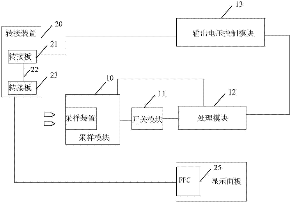
[0027] figure 2 It is a structural block diagram of the voltage calibration circuit provided by the embodiment of the present invention. The voltage calibration circuit can provide accurate programmin...


PUM


Abstract

The embodiment of the invention discloses a voltage calibration circuit and burning equipment thereof. The circuit comprises a sampling module, a switch module, a processing module and an output voltage control module. A sampling device of the sampling module is used for comparing an input reference voltage received by the input end with an input voltage and then outputting a corresponding control signal to the switch module; the switch module is used for communicating a path between the sampling module and the processing module when a control signal is a communication control signal; the processing module is used for obtaining the input voltage and the output reference voltage and generating the pulse signal according to the obtained input voltage and the output reference voltage; the output voltage control module is used for generating the accurate burning output voltage on the basis of the control pulse signal provided by the processing module and then obtaining the accurate burning input voltage after switching of a switching device so as to provide the burning input voltage for a display panel. The voltage calibration circuit and the burning equipment thereof can provide the accurate burning voltage parameter for the display panel and ensure the reliability of the burning process.

Description

technical field [0001] The invention relates to the field of display technology, in particular to a voltage calibration circuit and a programming device thereof. Background technique [0002] Usually, the display panel needs to use the programming device to write the programming data required for normal operation, such as voltage, before use. The programming data is usually stored in an OTP (One Time Programmable, one time programmable) chip or MTP (Multi Time Programmable, one time programmable) chip of the display panel. figure 1 It is a structural schematic diagram of the connection between the existing burning device and the display panel. Such as figure 1 As shown, the programming device 5 is sequentially connected to the FPC (Flexible Printed Circuit board, flexible printed circuit board) 9 provided on the display panel through the first adapter board 6 , the adapter wire 7 , and the second adapter board 8 . During the programming process of the above-mentioned disp...

Claims


Application Information

Patent Timeline
Patent Type & Authority Patents(China)
IPC IPC(8): G06F9/455G02F1/133G09G3/36
CPCG05F1/561G06F8/61
Inventor 陈心全朱修剑葛明伟
Owner KUNSHAN GO VISIONOX OPTO ELECTRONICS CO LTD
Why Eureka
Try Eureka