
Tooling frame able to adhere to tin

Inactive Publication Date: 2005-10-04
PEGATRON
View PDF13 Cites 0 Cited by
  • Summary
  • Abstract
  • Description
  • Claims
  • Application Information

AI Technical Summary

Benefits of technology

[0005]The primary objective of the present invention is to provide a tooling frame which is able to adhere to tin and thus can reduce the occurrence of tin bridge and poor tin filling defects in circuit boards so as to raise the soldering quality of circuit boards.
[0009]The tin adhesive apparatus of this invention can suck surplus tin both after the circuit board is transported through the stannic furnace for tin filling and during tin shedding, and thus can decrease the undesired tin bridge or poor tin filling and improve the output yield of the stannic furnace. Therefore, this invention can save labor costs and enhance quality of products.

Problems solved by technology

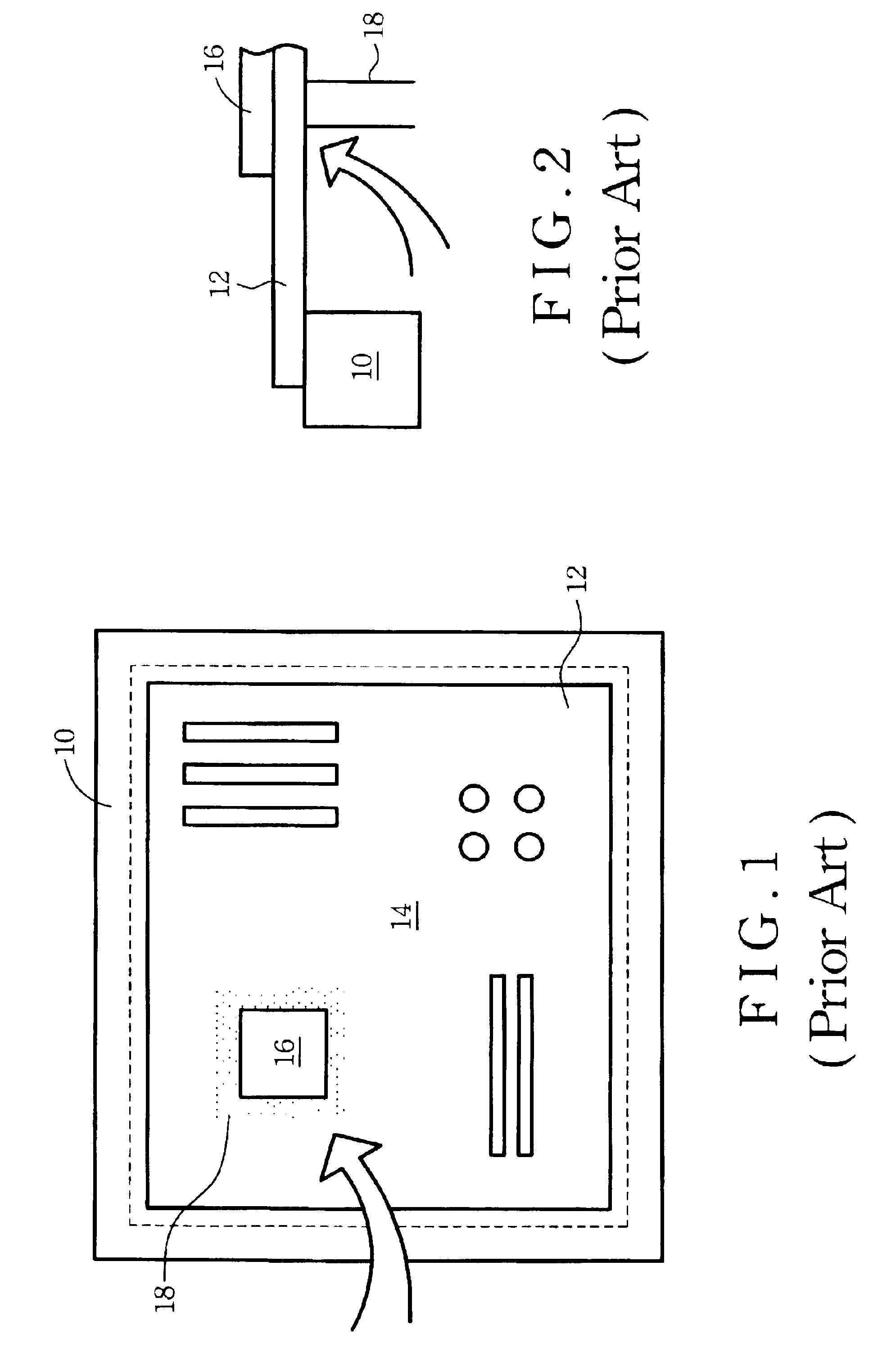
This leads that the related circuit board layout design becomes more sophisticated and complicated and that the manufacturing processes for plugging and tin soldering of circuit boards meet with considerable difficulties.
Although the above-mentioned problems may be later remedied by operators to remove the tin bridge and poor filling tin in order to maintain the soldering quality of the circuit board, such an action not only increases labor costs, but also the quality of circuit boards becomes uncontrollable due to the human factor.

Method used


Image

  • Tooling frame able to adhere to tin
  • Tooling frame able to adhere to tin
  • Tooling frame able to adhere to tin

Examples


Embodiment Construction

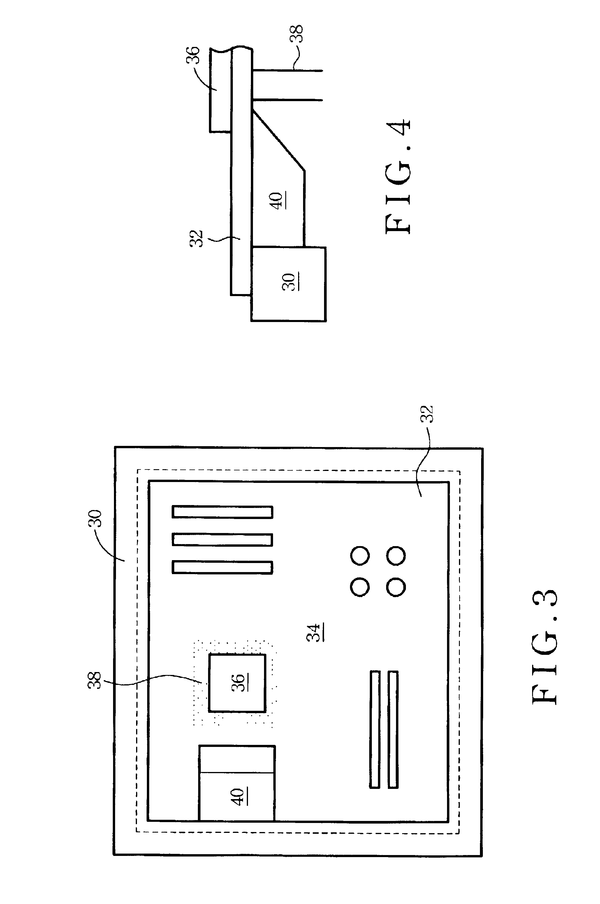
[0015]A tooling frame having an ability to adhere to tin of this invention is disclosed, wherein a tin adhesive apparatus having a tin adhesive material mounted thereon can suck surplus tin on the contact pins of the chips after the circuit board is transported through the stannic furnace for tin filling, so that the undesired tin bridge or poor tin filling taken place at the surface of the circuit board will be avoided and the soldering quality of the circuit board can be enhanced. The detailed description of the present invention is given by the following best mode for illustration.

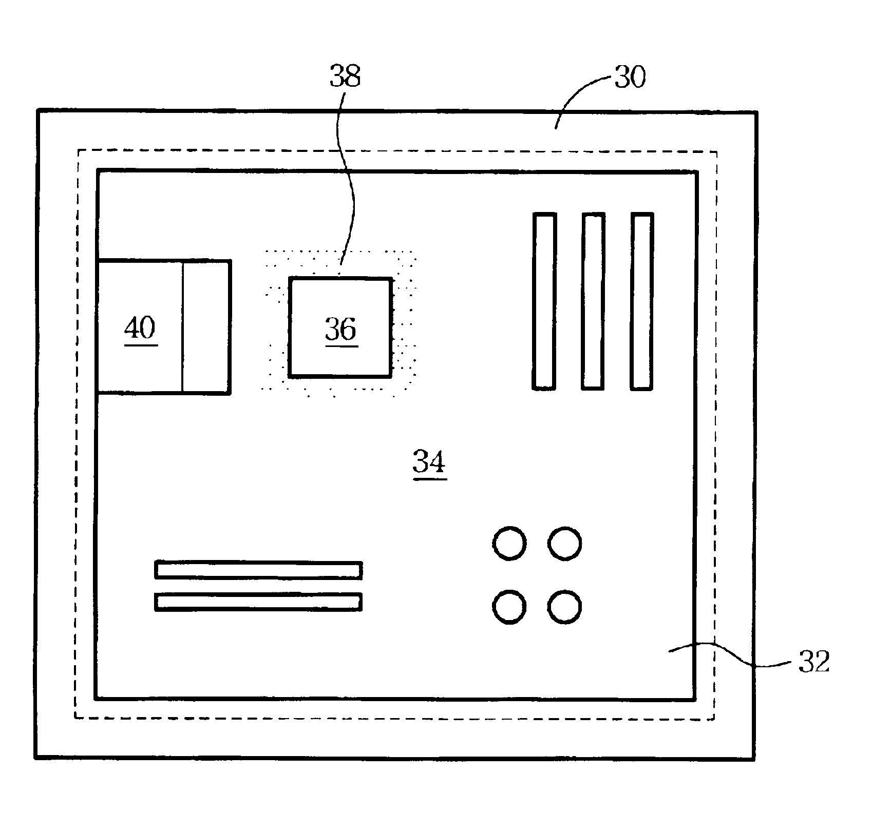
[0016]Please refer to FIG. 3, which is a schematic diagram of a bottom view of a tooling frame having an ability to adhere to tin in accordance with the present invention. The tooling frame comprises a main frame 30 designed in accordance with the shape and dimension of a circuit board 12. The rims of the circuit board 32 are held on the main frame 30. The surface 34 of the circuit board 32 to be solder...


PUM

PropertyMeasurementUnit
Angleaaaaaaaaaa
Shapeaaaaaaaaaa
Dimensionaaaaaaaaaa

Abstract

A tooling frame with an ability to adhere to tin is disclosed, which is a frame structure used to support a circuit board passing through a stannic furnace to be soldered. The tooling frame is characterized in that a tin adhesive apparatus having a tin adhesive material is mounted at an appropriate location of the tooling frame so as to suck surplus tin on said circuit board both after the circuit board is transported through the stannic furnace for tin filling and during tin shedding and to improve quality of soldering.

Description

FIELD OF THE INVENTION[0001]The present invention relates to a frame structure for supporting a circuit board which passes through a stannic furnace to be soldered, more particularly, to a tooling frame having an ability to adhere to tin.BACKGROUND OF THE INVENTION[0002]With the rapid advances in the integrated circuit (IC) packaging technology and the great promotion of operation performance, not only multi-media computers are widely favored by consumers, but also popularization of computers and the related peripheral products are accelerated. However, because of improvements in IC's operation performance, the number of the packaging contact pins of various components is also greatly increased. This leads that the related circuit board layout design becomes more sophisticated and complicated and that the manufacturing processes for plugging and tin soldering of circuit boards meet with considerable difficulties. In current production procedures in assembly of circuit boards, the ma...

Claims


Application Information

Patent Timeline
IPC IPC(8): B23K3/08B23K3/00H05K3/34
CPCB23K3/087H05K3/3468H05K2203/0165H05K2203/0169H05K2203/046
Inventor LEE, MING-JERYEN, CHIH-JU
Owner PEGATRON
Learn More