OLED display module, display device and preparation method of the display module

A technology for display modules and display screens, which is applied to identification devices, static indicators, instruments, etc., can solve the problems of lowering the yield rate of display modules and increasing the difficulty of design of display modules, so as to reduce design risks and ensure size, and the effect of improving yield

Active Publication Date: 2020-01-03
WUHAN CHINA STAR OPTOELECTRONICS TECH CO LTD
View PDF5 Cites 0 Cited by
  • Summary
  • Abstract
  • Description
  • Claims
  • Application Information

AI Technical Summary

Problems solved by technology

The shrinkage of pads and the density of data traces will inevitably lead to an increase in the difficulty of display module design and a decrease in the output yield of display modules

Method used


Image

  • OLED display module, display device and preparation method of the display module
  • OLED display module, display device and preparation method of the display module
  • OLED display module, display device and preparation method of the display module

Examples


Embodiment Construction

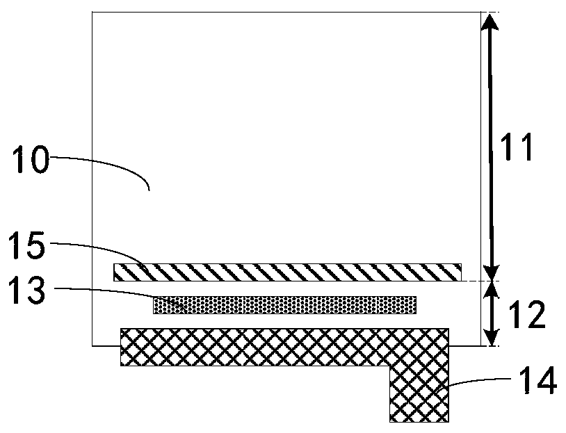
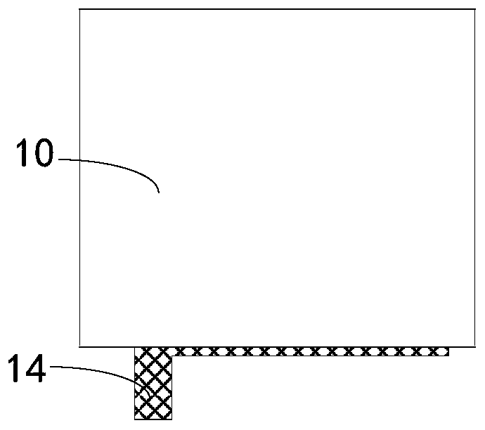
[0030] refer to Figure 3A and Figure 3B , in the first embodiment of the present invention, the OLED display module includes: an OLED display 20 , a source input terminal 21 , a conductive coating 22 , a driver chip 23 and a flexible circuit board 24 .

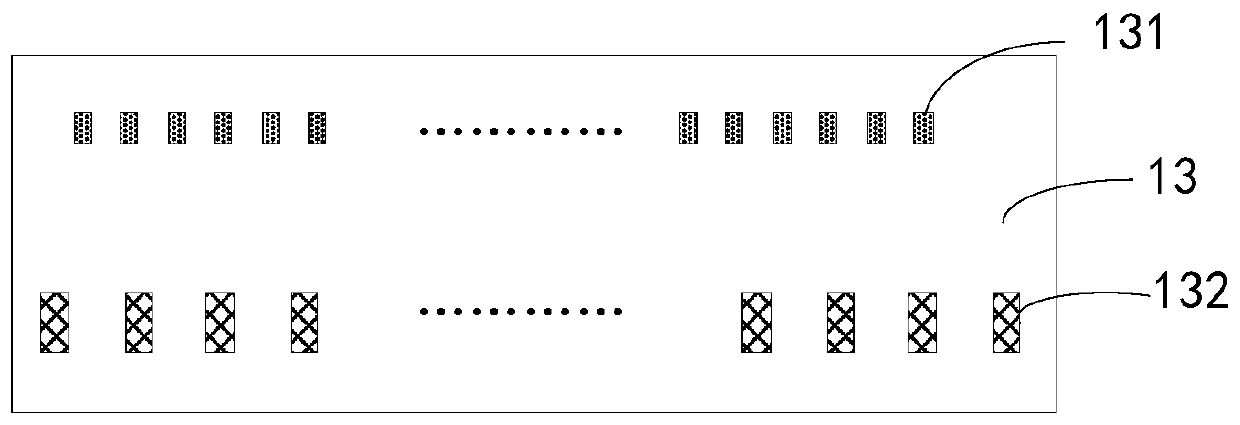
[0031] A source input terminal 21 is provided on the front of the OLED display 20 . In this embodiment, the source input terminal 21 includes a first source input terminal 211 and a second source input terminal 212, and the first source input terminal 211 and the second source input terminal 212 are arranged oppositely, which are located on the OLED display The upper and lower ends of the screen 20. It can be understood that, in other embodiments, the first source input terminal 211 and the second source input terminal 212 may also be located at opposite left and right ends of the OLED display 20 .

[0032] The conductive coating 22 is located on the back of the OLED display 20 , and the conductive coating 22 is electrica...


PUM


Abstract

Provided are an OLED display module and a manufacturing method thereof. The OLED display module comprises an OLED display screen (20) and a driver chip (21). The OLED display screen (20) is provided with a display signal input end (22). The driver chip (21) is fixed to a back surface of the OLED display screen (20) and is provided with a driving signal output end (211). Signals outputted by the driving signal output end (211) are led from at least two ends of the driver chip (21) and eventually inputted to the display signal input end (22). The OLED display module having the above structure can reduce design risk and increase yield.

Description

technical field [0001] The invention relates to the field of display technology, in particular to an OLED display module, a display device and a preparation method of the display module. Background technique [0002] With the development of technology, electronic devices are becoming more and more common. For electronic equipment to display normally, in addition to a display screen, a driver chip and a flexible circuit board are also provided. [0003] Figure 1A It is a structural schematic diagram of the front of the display module in the prior art, Figure 1B It is a structural schematic diagram of the back of the display module. The front of the display screen 10 will leave a large part of the lower border (border) area 12 below the effective display area 11, which is used to place the driver chip 13 and the flexible circuit board 14, so as to provide the drive signal to the source input terminal 15 and drive the chip. 13. Through its own input pad (Input pad), output...

Claims


Application Information

Patent Timeline
Patent Type & Authority Patents(China)
IPC IPC(8): G09F9/33G09G3/3208
CPCG09F9/33G09G3/3208
Inventor 安泰生
Owner WUHAN CHINA STAR OPTOELECTRONICS TECH CO LTD
Why Eureka
Try Eureka