
Rubber ring feeding mechanism of solenoid valve diaphragm assembly machine

A rubber ring, solenoid valve technology, applied in metal processing, metal processing equipment, manufacturing tools, etc., can solve the problems of long assembly cycle, high cost, easy occurrence of defective products, etc., to achieve compact structure, neat feeding processing, saving The effect of labor

Inactive Publication Date: 2016-11-23
WUHU HANGTIAN SPECIAL CABLE FACTORY
View PDF8 Cites 4 Cited by
  • Summary
  • Abstract
  • Description
  • Claims
  • Application Information

AI Technical Summary

Problems solved by technology

[0002] The solenoid valve diaphragm is also called the pulse valve diaphragm. It is the blowing air circuit switch of the dust cleaning system of the pulse bag filter and the key accessory for the normal operation of the solenoid valve. The existing solenoid valve diaphragm is mainly assembled manually. Solenoid valve diaphragm assembly has a high degree of difficulty, manual assembly has human factors, prone to defective products, and the assembly cycle is long, low in efficiency and high in cost. In view of this, based on the defects and deficiencies of the existing technology, a solenoid valve is designed Rubber ring feeding mechanism of diaphragm assembly machine

Method used


Image

  • Rubber ring feeding mechanism of solenoid valve diaphragm assembly machine
  • Rubber ring feeding mechanism of solenoid valve diaphragm assembly machine
  • Rubber ring feeding mechanism of solenoid valve diaphragm assembly machine

Examples


Embodiment Construction

[0018] The preferred embodiments of the present invention will be described in detail below in conjunction with the accompanying drawings, so that the advantages and features of the invention can be more easily understood by those skilled in the art, so as to define the protection scope of the present invention more clearly.

[0019] see Figure 1 to Figure 6 , the embodiment of the present invention includes:

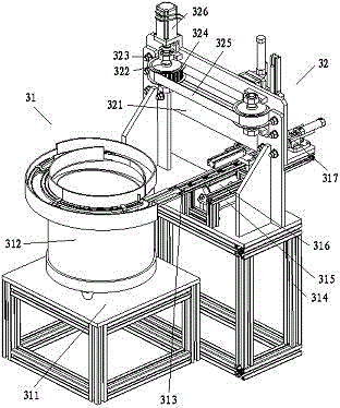
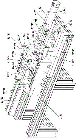
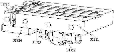
[0020] A rubber ring feeding mechanism of a solenoid valve diaphragm assembly machine, the rubber ring feeding mechanism of the solenoid valve diaphragm assembly machine includes a rubber ring feeding device 31 and a rubber ring feeding device 32, the rubber ring feeding device The rubber ring mounting frame 314 of 31 is equipped with a rubber ring feeding device 32, and the rubber ring feeding device 31 also includes a rubber ring frame 311, a rubber ring vibrating tray 312, a rubber ring feeder 313, a rubber ring support 315, rubber ring vibrator 316 and rubber ring...


PUM


Abstract

The invention discloses a rubber ring feeding mechanism of a solenoid valve diaphragm assembly machine. The rubber ring feeding mechanism of the solenoid valve diaphragm assembly machine comprises a rubber ring supplying device and a rubber ring feeding device. The rubber ring feeding device is arranged on a rubber ring installing rack of the rubber ring supplying device; the rubber ring supplying device also comprises a rubber ring rack, a rubber ring vibrating plate, rubber ring feeders, a rubber ring support, a rubber ring vibrator and rubber ring discharging units; the two rubber ring feeders are arranged on a discharge hole of the rubber ring vibrating plate; the rubber ring installing rack is arranged under the rubber ring feeders; the rubber ring support is arranged on the rubber ring rack; the rubber ring vibrator is arranged on an upper flat plate of the rubber ring support; the rubber ring feeders are fixed to the rubber ring vibrator; and the rubber ring discharging units are arranged on discharging holes of the rubber ring feeders. Through the manner, the rubber ring feeding mechanism of the solenoid valve diaphragm assembly machine provided by the invention is compact in structure, and can be used for feeding rubber rings automatically, efficiently and trimly instead of manpower.

Description

technical field [0001] The invention relates to the field of mechanical automation, in particular to a rubber ring feeding mechanism of a solenoid valve diaphragm assembly machine. Background technique [0002] The solenoid valve diaphragm is also called the pulse valve diaphragm. It is the blowing air circuit switch of the dust cleaning system of the pulse bag filter and the key accessory for the normal operation of the solenoid valve. The existing solenoid valve diaphragm is mainly assembled manually. Solenoid valve diaphragm assembly has a high degree of difficulty, manual assembly has human factors, prone to defective products, and the assembly cycle is long, low in efficiency and high in cost. In view of this, based on the defects and deficiencies of the existing technology, a solenoid valve is designed The rubber ring feeding mechanism of the diaphragm assembly machine. Contents of the invention [0003] The technical problem mainly solved by the present invention i...

Claims


Application Information

Patent Timeline
Patent Type & Authority Applications(China)
IPC IPC(8): B23P19/08B23P19/00
CPCB23P19/001B23P19/084
Inventor 鲍杨建
Owner WUHU HANGTIAN SPECIAL CABLE FACTORY
Learn More