Method and device for detecting long persistent luminescence of optical network unit (ONU)

A technology of long emission and light detection, which is applied in the field of passive optical network to solve the effect of ONU long emission

Active Publication Date: 2016-11-23
RAISECOM TECH
View PDF6 Cites 2 Cited by
  • Summary
  • Abstract
  • Description
  • Claims
  • Application Information

AI Technical Summary

Problems solved by technology

[0004] The embodiment of the present invention provides a method and device for detecting ONU long light emission, which can effectively solve the problem of ONU long light emission when the CPU itself is also working abnormally

Method used


Image

  • Method and device for detecting long persistent luminescence of optical network unit (ONU)
  • Method and device for detecting long persistent luminescence of optical network unit (ONU)
  • Method and device for detecting long persistent luminescence of optical network unit (ONU)

Examples


Embodiment 1

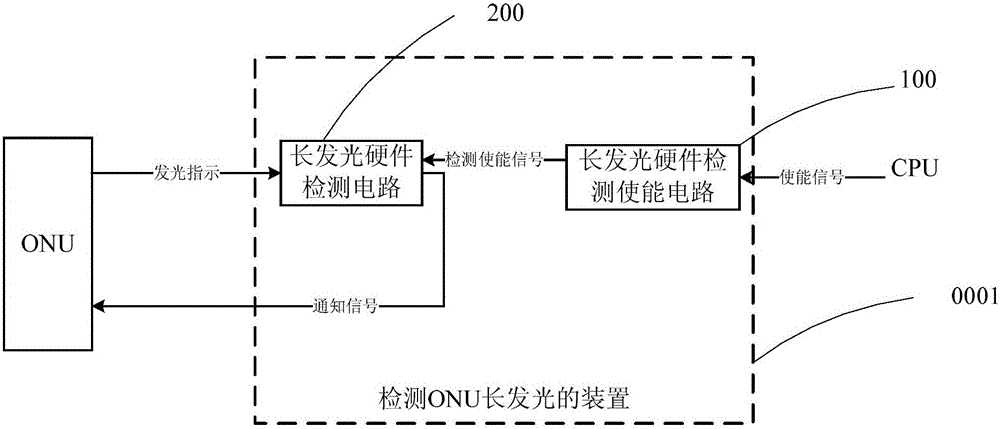
[0054] figure 1 It is a schematic block diagram of a device for detecting ONU long luminescence according to an embodiment of the present invention, such as figure 1 As shown, the device 0001 for detecting ONU long luminescence in this embodiment includes:

[0055] The long-lighting hardware detection enabling circuit 100 is used to send an effective detection enabling signal to the long-lighting hardware detection circuit 200 when receiving an effective enabling signal sent by the CPU, or when it is judged that the CPU is abnormal;

[0056] The long-lighting hardware detection circuit 200 is configured to detect that the duration of the light-emitting indication signal of the ONU is greater than a predetermined longest light-emitting time when receiving the effective detection enable signal sent by the long-light-emitting hardware detection enabling circuit. time, output a notification signal notifying the ONU to turn off the power supply; otherwise, output a notification si...

Embodiment 2

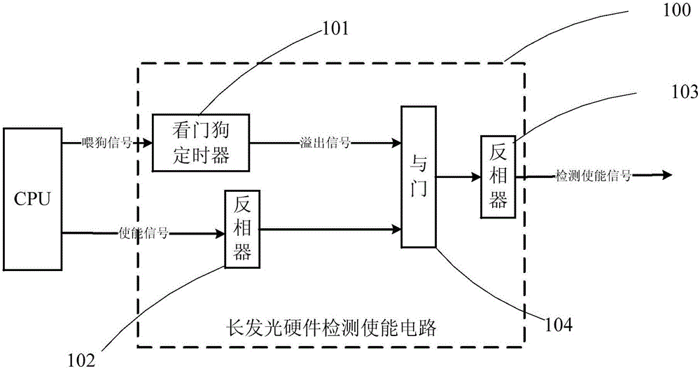
[0059] figure 2 It is a schematic block diagram of detecting ONU long luminescence according to an embodiment of the present invention, such as figure 2 As shown, the long light emitting hardware detection enabling circuit 100 of this embodiment includes: a watchdog timer 101, an inverter 102, an inverter 103 and an AND gate 104, wherein,

[0060] The watchdog timer 101 receives the dog feeding signal of the CPU, and when the duration of the dog feeding signal exceeds a preset timing value, an overflow signal is sent to the AND gate 104, otherwise the CPU normal indication signal is output;

[0061] The inverter 102 receives the enable signal sent by the CPU, and outputs the signal after the "inversion" operation of the enable signal to the AND gate 104;

[0062] The AND gate 104 performs an "AND" operation on the received overflow signal or the CPU normal indication signal and the "inverted" signal of the enable signal, and outputs the signal after the "AND" operation to t...

Embodiment 3

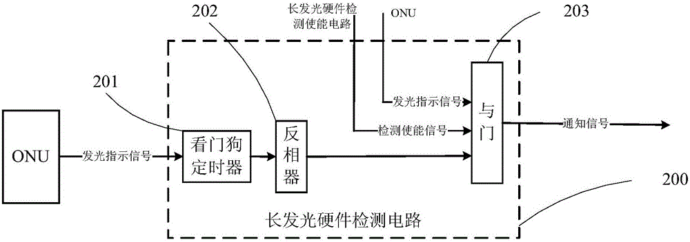
[0069] image 3 It is a schematic block diagram of a device for detecting ONU long luminescence according to an embodiment of the present invention, such as image 3 As shown, the long light emitting hardware detection circuit 200 of this embodiment includes: a watchdog timer 201, an inverter 202 and an AND gate 203, wherein,

[0070] Watchdog timer 201 receives the light-emitting indication signal of the ONU, and when the duration of the light-emitting indication signal is greater than a predetermined timing time, outputs a long light-emitting signal (here is an overflow signal of the watchdog timer) to the feedback signal. Phaser 202; when the duration of the light-emitting indication signal is not longer than a predetermined timing time, output a normal light-emitting signal to the inverter 202, wherein the predetermined timing time is a predetermined longest light-emitting time;

[0071] The inverter 202 performs an "inversion" operation on the received long luminescence ...


PUM


Abstract

The invention provides a device for detecting the long persistent luminescence of an optical network unit (ONU). The device comprises a long persistent luminescence hardware detection enabling circuit for sending an effective detection enabling signal to a long persistent luminescence hardware detection circuit upon receiving an effective enabling signal sent from a CPU or judging the CPU to be in the abnormal state; the long persistent luminescence hardware detection circuit used for outputting a notifying signal to notify the ONU to turn off a power supply when detecting that the duration of a light-emitting indication signal is larger than a predetermined longest light-emitting time after receiving the detection enabling signal sent from the long persistent luminescence hardware detection enabling circuit or outputting a notifying signal to notify the ONU not to turn off the power supply when detecting that the duration of the light-emitting indication signal is not larger than the predetermined longest light-emitting time. According to the technical scheme of the invention, the long persistent luminescence problem of the ONU is effectively solved even under the condition that the CPU itself works abnormally. The ONU, with the long persistent luminescence problem, is automatically drawn out of the production line. Therefore, the whole network is not affected at all.

Description

technical field [0001] The present application relates to but not limited to the field of passive optical network, especially a method and device for detecting long-term emission of an ONU (Optical Network Unit, optical network unit). Background technique [0002] Since the release of IEEE (Institute of Electrical and Electronics Engineers, Institute of Electrical and Electronics Engineers) 802.3ah, the current related solutions and equipment have basically matured. Along with the rapid development of Ethernet technology, FTTH (fiber-to-the-home) is also vigorously developed. Under the background of the comprehensive popularization of digital networks, users also have extremely high requirements for network quality, so the stable operation of PON (Passive Optical Network, Passive Optical Network) system becomes very important. [0003] As the user-end equipment in the PON system, the ONU is installed in a complex and diverse environment. Some are placed in the user's home, ...

Claims


Application Information

Patent Timeline
Patent Type & Authority Applications(China)
IPC IPC(8): H04B10/079
CPCH04B10/0791H04B10/0795
Inventor 谢燕根卫全康胡海智马文军
Owner RAISECOM TECH
Why Eureka
Try Eureka