
Street lamp control system for lighting up and down in the middle of the night

A street light control and street light technology, applied in energy-saving control technology, light circuit layout, light source, etc., can solve problems such as pedestrian changes

Active Publication Date: 2019-01-15
SHANGHAI LONG JOIN ELECTRONICS
View PDF7 Cites 0 Cited by
  • Summary
  • Abstract
  • Description
  • Claims
  • Application Information

AI Technical Summary

Problems solved by technology

Therefore, the current way of controlling street lamps through light sensors cannot well meet people's requirements.
[0004] In addition, the lighting intensity of street lamps in the existing control method is the same and cannot be changed according to the number of pedestrians

Method used


Image

  • Street lamp control system for lighting up and down in the middle of the night
  • Street lamp control system for lighting up and down in the middle of the night

Examples


Embodiment 1

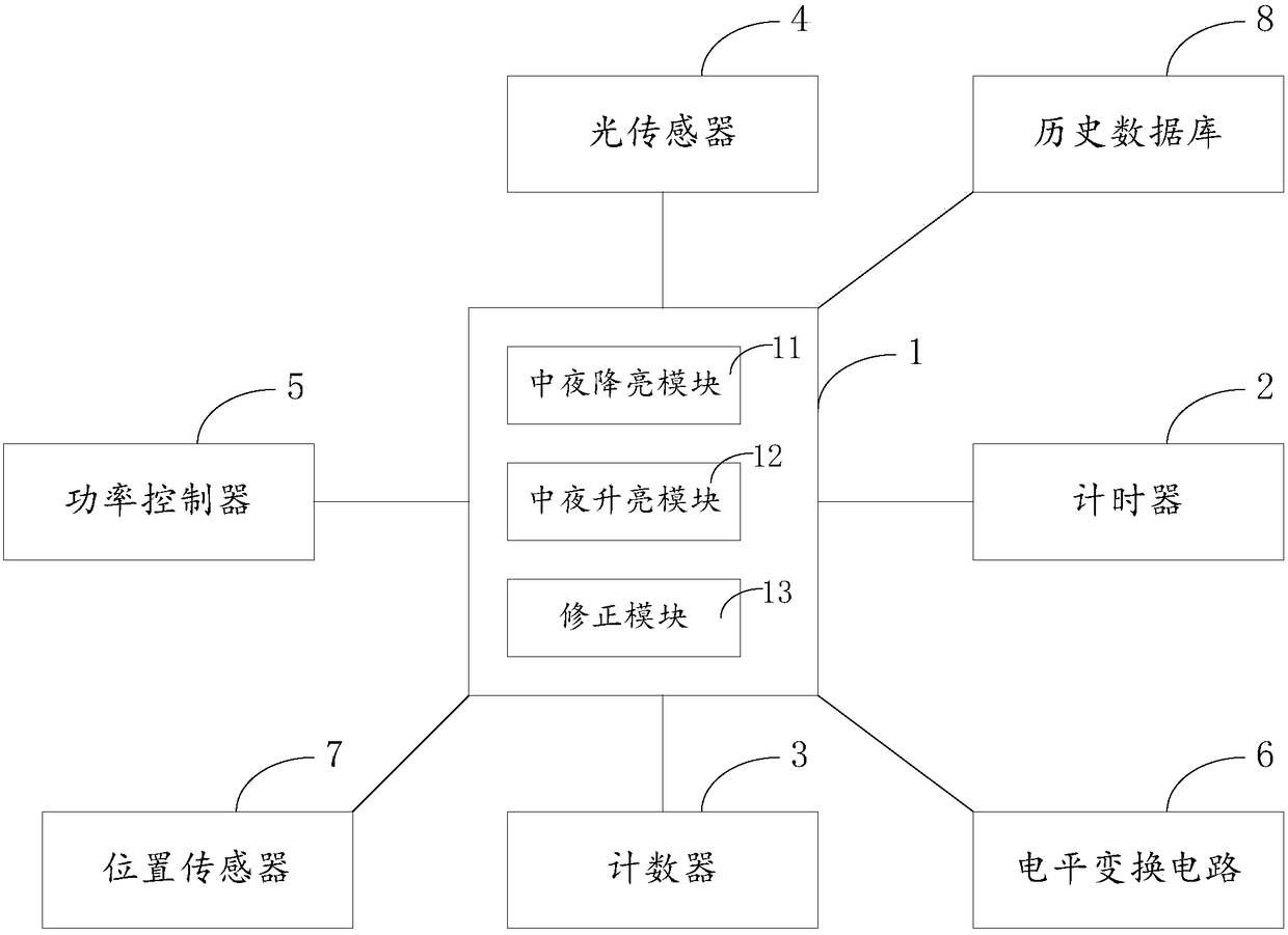
[0049] see figure 1 , the present invention discloses a street lamp control system for lighting up and down at night. The street lamp control system includes: a main controller 1, a timer 2, a counter 3, a position sensor 7, at least one light sensor 4, and a power controller 6. Historical database 8.

[0050] The main controller 1 is respectively connected with a timer 2 , a position sensor 7 , each light sensor 4 , a power controller 6 , and a historical database 8 .

[0051] The timer 2 is used to obtain time information, the position sensor 7 is used to obtain position change information of surrounding moving objects, the light sensor 4 is used to obtain light intensity information, the power controller 6 is used to control the power of street lamps, and the historical database 8 is used to To record the light-on time, light-off time, and power change time information of each time cycle (or only record the light-on time of the previous cycle).

[0052] The main controlle...

Embodiment 2

[0069] A street lamp control system for lighting up and down at night, the street lamp control system includes: a main controller, a timer, at least one light sensor, a power controller, and a historical database.

[0070] The main controller is respectively connected with the timer, each light sensor, the power controller, and the historical database.

[0071] The timer is used to obtain time information, the position sensor is used to obtain the position change information of surrounding moving objects, the light sensor is used to obtain light intensity information, the power controller is used to control the power of street lamps, and the historical database is used to record the previous cycle of turning on the lights duration.

[0072] The main controller includes a middle-night light-reducing module and a middle-night brightening module.

[0073] The mid-night lighting module is used to control the street lamp through the power controller to reduce the power of the stre...


PUM


Abstract

The invention discloses a street lamp control system achieving brightness boosting and brightness reducing at midnight. The street lamp control system comprises a main controller, a timer, at least one optical sensor, a power controller and a historical database; the main controller comprises a midnight brightness reducing module and a midnight brightness boosting module; the midnight brightness reducing module is used for controlling a street lamp to be set to reduce the power of the street lamp in the first moment through the power controller, and the time for reducing the power of the street lamp is the start-up time of the street lamp in the current cycle plus 40%-50% of the turn-on duration of the previous cycle; the midnight brightness boosting module is used for controlling the street lamp to be set to increase the power of the street lamp in the second moment through the power controller, and the time for increasing the power is the first time of the current cycle plus 30%-40% of the turn-on duration of the previous cycle. According to the street lamp control system achieving brightness boosting and brightness reducing at midnight, the illuminating brightness of the street lamp can be controlled according to different time requirements.

Description

technical field [0001] The invention belongs to the technical field of street lamp control, and relates to a street lamp control system, in particular to a street lamp control system for turning on and off at night. Background technique [0002] With the advancement of technology, the control method of street lights is becoming more and more intelligent; street lights are usually controlled by a fixed duration, such as setting the lights to turn on at 6 o'clock in the evening and turn off the lights at 6 o'clock in the morning. However, this control method cannot be controlled for different weather conditions (such as rainy weather); at the same time, because the length of day and night is constantly changing, the method of controlling the lights on and off at a fixed time cannot meet the needs of pedestrians. [0003] Another control method is to set a light sensor to sense the light intensity through the light sensor, and switch the street light when it reaches a critical ...

Claims


Application Information

Patent Timeline
Patent Type & Authority Patents(China)
IPC IPC(8): H05B37/02
CPCH05B47/105H05B47/11H05B47/16Y02B20/40
Inventor 张敏胡延军
Owner SHANGHAI LONG JOIN ELECTRONICS
Learn More