Edge turning jig and edge turning method using same
A jig and flanging technology, applied in the mechanical field, can solve the problems of low production efficiency, unguaranteed size and angle, and inability to meet the workpiece production process, so as to improve production efficiency, meet process requirements and production requirements, and meet The effect of diversified production
- Summary
- Abstract
- Description
- Claims
- Application Information
AI Technical Summary
Problems solved by technology
Method used
Image
Examples
Embodiment 1
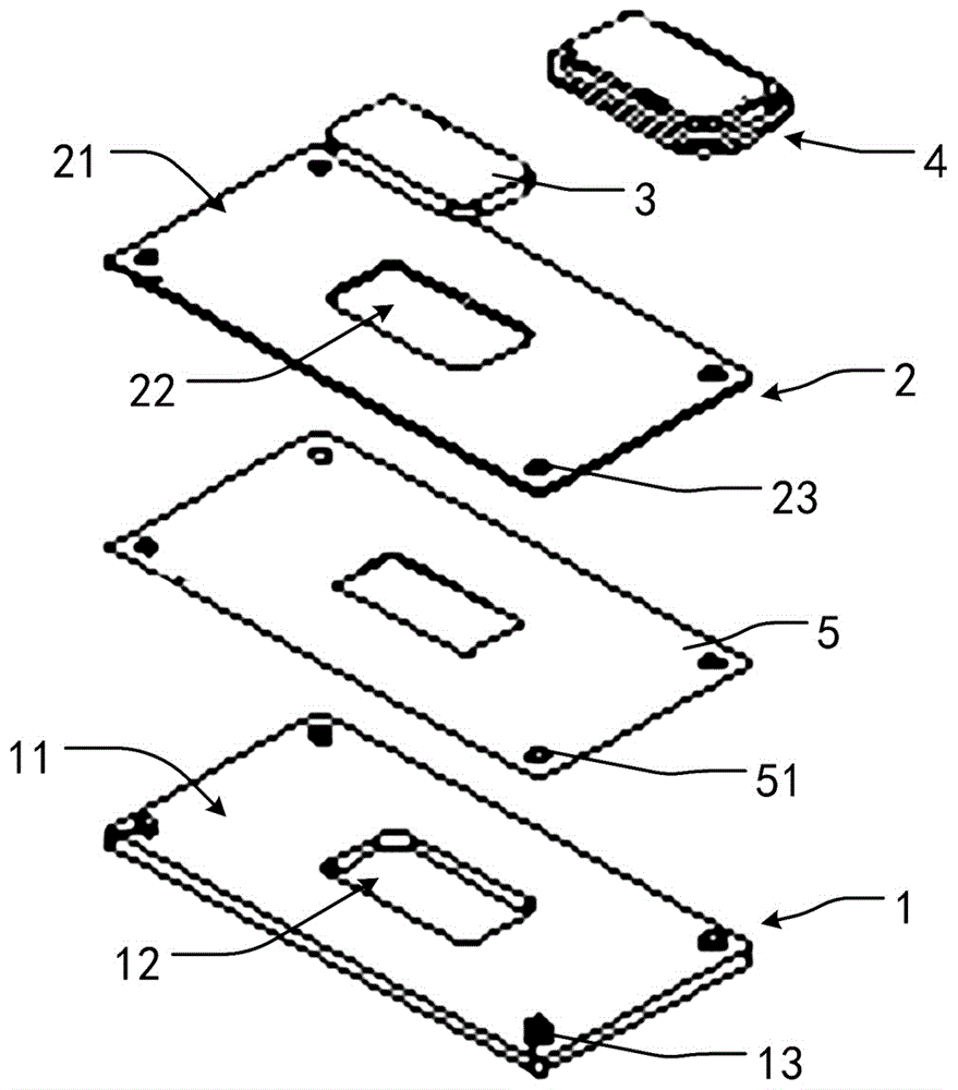
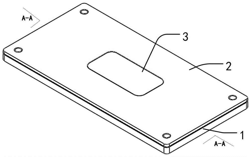
[0046] Embodiment 1: as figure 1 As shown, a flanging fixture includes a lower die 1 , an upper die 2 , a first punch 3 and a second punch 4 .
[0047] The lower mold 1 is a cuboid. The lower mold 1 includes a first mounting surface 11 and a first flange hole 12 . Wherein, the installation surface includes four upright posts 13 , and the upright posts 13 are arranged at four corner ends of the cuboid lower mold 1 . The first flanging hole 12 is provided in the middle of the lower mold 1. For the convenience of description, in this embodiment, the flanging hole is a cuboid. The first mounting surface 11 is a plane.
[0048] This upper mold 2 is also a cuboid. The upper mold 2 includes a second mounting surface 21 and a second flange hole 22 . Wherein, the second installation surface 21 is opposite to the first installation surface 11 , and the size and shape of the first burring hole 12 are consistent with the size and shape of the second burring hole 22 . The second moun...
Embodiment 2
[0053] Example 2, such as Figure 2 to Figure 7 As shown, a flanging method using a flanging jig includes the following steps.
[0054] S01: Fix the flanged sheet metal part 5 between the first installation surface 11 and the second installation surface 21 .
[0055] S02: Press the first punch 3 into the second flange hole 22 .
[0056] S03: using the first punch 3 to punch holes.
[0057] S04: Take off the upper mold 2, and turn over the surface of the sheet metal part 5.
[0058] S05: Utilize the second punch 4 to punch the raised edge of the sheet metal part 5 .
[0059] Further, the step S05 includes the following steps:
[0060] S051: Use the stamping part 42 of the second punch 4 to punch the turned-up side of the sheet metal part 5, so that the turned-up side is inclined outward.
[0061] S052: Use the plane of the limiting portion 41 of the second punch 4 to punch the inclined edge to complete the flanging.
PUM
 Abstract
Description
Claims
Application Information
 - R&D
- Intellectual Property
- Life Sciences
- Materials
- Tech Scout
- Unparalleled Data Quality
- Higher Quality Content
- 60% Fewer Hallucinations
Browse by: Latest US Patents, China's latest patents, Technical Efficacy Thesaurus, Application Domain, Technology Topic, Popular Technical Reports.
© 2025 PatSnap. All rights reserved.Legal|Privacy policy|Modern Slavery Act Transparency Statement|Sitemap|About US| Contact US: help@patsnap.com


